I’ve been playing around with some stepper motors with driver boards that I bought from eBay. They have a lot of potential and I’m planning to use them on an astronomy project… but more on that later.
The motors were £1.66 each including postage. Not the fastest delivery ever but then they were from Hong Kong.
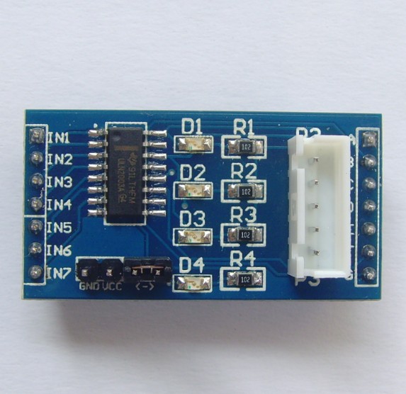
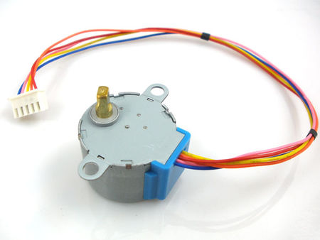
The actual boards which arrived were much nicer than those pictured on the eBay lot and were manufactured by LC Technology. Below is a picture of the actual board and the accompanying stepper motor and cable and here’s a link to the LC Tech page about the board. The stepper motors are all 5V so can be run off the Raspberry Pi’s 5V power supply pin.
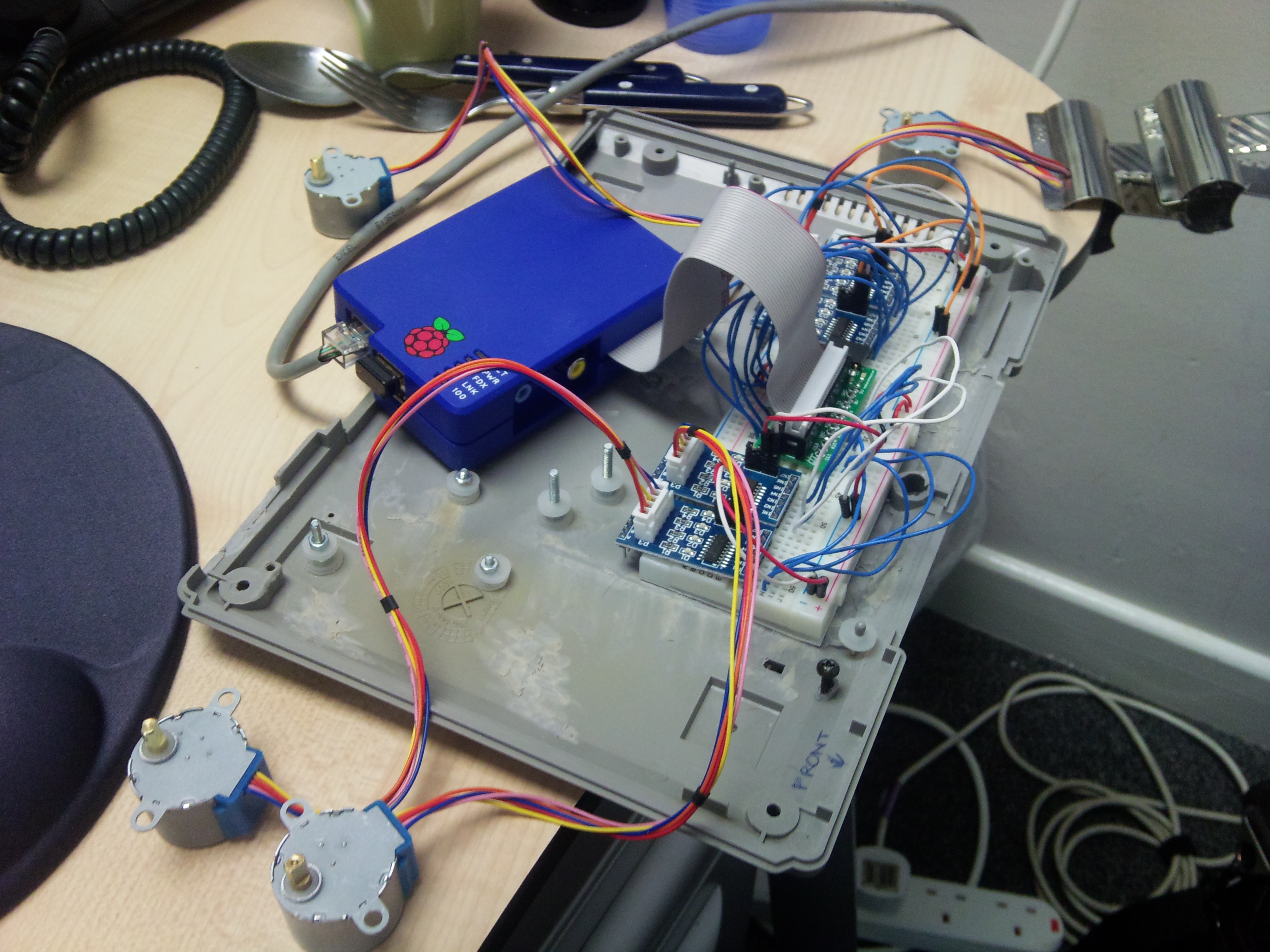
I’ve built this on a breadboard connected to the GPIO using a breakout board from HobbyTronics. It’s almost identical to the Pi Cobbler but has a nifty power light and 3.3v regulator on board. Plus they’re based in the UK, which helped with the postage at the time.
The stepper motors are then connected to the boards using a supplied cable. When the motor is working, the LEDs on the control board light up (in sequence, but they’re going so fast in the video above that you can’t really tell that).
I’ve put the Python code for this experiment on GitHub. The main Motor class was taken from work done by Stephen Phillips on his blog. Here’s his original post. My code is available at https://github.com/recantha/stepper-pi
There is a main driver script – test-all-motors.sh – which fires off 4 parallel runs of the test-motor.py script with 4 different sets of 4 GPIO pins.
For those interested, I am using the following physical pins as control pins for the motors: 8,10,12,16 and 18,22,24,26 and 3,5,7,11 and 15,19,21,23. Some of these pins have alternate uses (for example serial tx and rx) but it was necessary to use them as general output pins to get the 16 pins I needed.
What’s next?
Well, at the moment the motors each drive a bit of paper, just to show the movement. However, they have a reasonable amount of torque. So, I’m hoping to use them to control, hopefully on multiple axis, a webcam and eventually an official camera module. This will form the main part of the hardware for an upcoming astronomy project. The code for this is starting to be built as a GitHub repository.
[…] recantha I’ve been playing around with some stepper motors with driver boards that I bought from eBay. […]
I’ve been testing Stephen’s code with a single steeper configuration and have found that several consecutive move_to angle requests suffer from steps being missing due to the reset to 0 of all pins before the bigsteps for loop in the move_cw and move_acw functions. Eliminating the reset, the motor is able to execute multiple move_to angle requests and get back to the zero position without inaccuracies… Have you experienced something similar or am I getting it wrong?
And thanks for the post!
Hi. I had noticed that it wasn’t optimal. I’ve now switched to focussing just on the move_cw and move_acw rather than the move-to-a-specific-angle because of the type of project I’m doing.
Hi JOrtiz
I’m having similar inaccuracy problems as you – could you demonstrate your solution by showing some ‘corrected’ code. I’m having trouble spotting what changes to make.
Thanks
Chris
Hi Chris,
Apologies for the late response. I’ve been away…
Hope you find this useful:
#####################################################
#!/usr/bin/env python
# This code was originally written by Stephen C Phillips.
# It is in the public domain, so you can do what you like with it
# but a link to http://scphillips.com would be nice
# J Ortiz have modified the code to sort out apparent inaccuracy problem as per comment above. May 2013.
# J Ortiz: Movement is limited to position 3072 out of 4000 for the application this code is designed for. This restriction could be removed from the code for other purposes.
# J Ortiz: Caveats as usual, this works nicely and accurately for my application. You should make sure this is going to work in your system without causing any damage before you try. I take no responsibility for any damage this might cause.
# J Ortiz: Added simple command based interface to define required position (new).
# J Ortiz: It uses pickle to save current position on file so that it has memory and it can return to position 0 even after a switch off.
# It works on the Raspberry Pi computer with the standard Debian Wheezy OS and
from random import randrange
from time import sleep
import argparse
import pickle
import RPi.GPIO as GPIO
# Use BCM GPIO references instead of physical pin numbers
# BCM GPIO references equivalents: GPIO24, GPIO25, GPIO8, GPIO7
#GPIO.setmode(GPIO.BCM)
# Use physical references
# Physical pins to use 18,22,24,26
GPIO.setmode(GPIO.BOARD)
class Motor(object):
def __init__(self, pins):
# Define advanced sequence
# as shown in manufacturers datasheet
self.StepCount = 8
self.Seq = []
self.Seq = range(0, self.StepCount)
self.Seq[0] = [1,0,0,0]
self.Seq[1] = [1,1,0,0]
self.Seq[2] = [0,1,0,0]
self.Seq[3] = [0,1,1,0]
self.Seq[4] = [0,0,1,0]
self.Seq[5] = [0,0,1,1]
self.Seq[6] = [0,0,0,1]
self.Seq[7] = [1,0,0,1]
#SeqACW = Seq[::-1]
# Choose a sequence to use
self.pins = pins
self.deg_per_step = 5.625 / 64
self.steps_per_rev = int(360 / self.deg_per_step) # 4096
try:
with open(‘mpos.ini’): pass
except IOError:
f=open(‘mpos.ini’,’w’)
pickle.dump(0,f)
f.close()
f=open(‘mpos.ini’,’r’)
self.pos = pickle.load(f)
f.close()
self.seqpos = self.pos % 8
for p in self.pins:
# pfio.digital_write(p,0)
GPIO.setup(p, GPIO.OUT)
GPIO.output(p, 0)
#Initialise from latest/stored position
for i in range(0,4):
# pfio.digital_write(self.pins[i],self.Seq[self.seqpos][i])
GPIO.output(self.pins[i],self.Seq[self.seqpos][i])
def zero_pin(self):
for p in self.pins:
# pfio.digital_write(p,0)
GPIO.output(p, 0)
def _set_rph(self, rph):
“””Set the turn speed in RPH.”””
self._rph = rph
# T is the amount of time to stop between signals
self._T = (60.0 * 60.0 / rph) / self.steps_per_rev
# This means you can set “rph” as if it is an attribute and
# behind the scenes it sets the _T attribute
rph = property(lambda self: self._rph, _set_rph)
def move_to(self, target_pos):
# Make sure there is a 1:1 mapping between angle and stepper angle
steps = target_pos – self.pos
print “moving ” + `-steps` + ” steps to get to ” + `-target_pos` + ” ” + `self._T`
if target_pos < self.pos:
self._move_cw(-steps)
else:
self._move_acw(steps)
# self.pos = -target_pos
def _move_acw(self, steps):
for i in range(steps):
self.seqpos += 1
# If we reach the end of the sequence
# start again
if (self.seqpos==self.StepCount):
self.seqpos = 0
# Wait before moving on
sleep(self._T)
for pin in range(0, 4):
xpin = self.pins[pin]
if self.Seq[self.seqpos][pin]!=0:
# pfio.digital_write(xpin,1)
GPIO.output(xpin,1)
else:
# pfio.digital_write(xpin,0)
GPIO.output(xpin,0)
# Save new position in mpos.ini file
f=open('mpos.ini','w')
#pickle.dump(self.pos+i+1,f)
pickle.dump(self.pos+steps,f)
f.close()
def _move_cw(self, steps):
for i in range(steps):
self.seqpos -= 1
# If we reach the end of the sequence
# start again
if (self.seqpos 3072:
pos = 3072
print “Movements are limited to range (0, 3072)”
if pos < 0:
pos = 0
print "Movements are limited to range (0, 3072)"
m.move_to(-pos)
m.zero_pin()
GPIO.cleanup()
##################################################
Kind regards,
Jose Ortiz
Hi,
I followed the following tutorial
http://www.raspberrypi-spy.co.uk/2012/07/stepper-motor-control-in-python/
I have got the stepper motor to turn continuously in one direction and then in reverse. I have looked at your file test-motor.py . In this file where do you assign the 4 GPIO for the stepper motor. Basically I want the stepper motor to turn 90 degrees in one direction and then wait for a action and then turn 90 degrees
back to the original position.
Would you be able to point me in the right direction so I can get my stepper motor to turn a specified amount of degrees.
I am using the 5V Stepper Motor With ULN2003 Board.
Thanks.
thank you,
By the way can we use this GPIO to control cnc machines.
Thank you
“Probably” is the best answer I can give you. With sufficient circuitry and power supply, I’m sure you could hack it to do so.
Hi-
Cool project!
I’m Just starting out with the RPi 3 and wanted to build a project to run 3 stepper motors. I purchased a 4 motor controller shield with 4 motor drivers (A4988). Do you know how I would figure out how to connect the expansion board up to the RPi to run the motors from the expansion board? Controlling the simple single motor is pretty straightforward, but the extension board is a whole new world. Here’s what I’m using: https://smile.amazon.com/gp/product/B07DFK6ZJW/ref=ox_sc_act_title_1?smid=A28ZWXW3ZSVNZU&psc=1 I’m using this product because it could handle the slightly higher amperage than the requirements of my stepper motors (12v, 1.5A)– which also happen to be for 3d printers.
Thanks for the pointers!
Hi Tad. I’ve taken a look and I’m sorry but I don’t have a clue how you would hook that up! 🙁 Try asking on the Raspberry Pi forums – give them as much detail as you possibly can and hopefully someone will be able to help!
No worries. Thanks for taking a look, I appreciate it!
Tad