For a few years, I have been following the work of Martin Mander, a hobbyist with a passion for refurbishing and repurposing vintage electrical equipment. Recently, Martin repurposed a 1970s transistor radio to create an internet radio. This inspired me to look around to see what I could find to do something similar.
I came across a radio from 1996 on eBay – an R757 from Surrey-based manufacturer Roberts, who are now based in the West Midlands. If you want to do what I did and repurpose one, they’re pretty regularly available from what I have been able to determine.

I chose this one in particular because it was listed as being faulty. This appealed to me because I didn’t really want to rip the innards out of a perfectly fine piece of technology.
Disassembly
The first thing to do in any refurbishment project is, of course, to take it all apart and clean it up. The bottom of the radio is just a wooden plate with a single screw holding it on. This is so you can fit a battery if you want to make the radio portable.

The insides revealed, I could see that I would need to take it completely apart to get at anything inside. In particular, my ambition was to use as many of the knobs and switches as I could, so the top plastic part would need to be accessible for hacking. The handle was easy enough to remove (might as well make a proper job of it!)

Then the back could come off. This was interesting – a mixture of glue and half-nails held the back on – plenty of sharp bits to cut yourself on!

As you can see, there’s a bit of mould growing on it – probably from being stored in a garage or a shed! I still don’t quite know what to do about that – suggestions in the comments if there’s some sort of treatment I can get.
I still couldn’t remove the top as it was firmly stuck to the front, so I peeled off the leather-coated wooden bit at the top and… oops!
It seems that the wood and the glue conspired to help me rip a bit of the casing. Never mind, plenty left and I could glue it back together when reassembling.
This means I was now left with (most of) the front and top.

The top came away fairly easily (it was held in by the sides) and I was soon left with the main assembly of the top plate and the PCB.

Let’s see what we have. The top plate has the main PCB attached to it, as well as a small PCB connected to the volume/on-off dial. Also on the top plate is a tube wrapped in wire (which I assume is the tuning part of the radio). Of particular note are the four switches in the middle – I wanted to re-use those if I could. A great deal of de-soldering was in my near future, I realised. The output of the radio, as you can see, is an 8 ohm, 1W speaker. At the back of my mind, I had an inkling that 8 ohms was too much. Not knowing much about what that means, however, I still held onto the hope of using the original speaker if I could.
Detaching the circuit board from the top plate was fairly simple – a few screws.
I love that, even in the 1990s, bits were held on with tape!
Let’s take a look at the PCB a little bit to explain something:

The tuning dial was not a potentiometer at all, I realised. Instead, it was a continuous-rotation dial with a D-shaft to accomodate the knob. This dial had some thin string or elastic attached. The string then went around the top plate, moved a red indicator under the laminate (which shows what station you’re on) and then attached to a black circular apparatus (pictured). This then, somehow, changed the frequency that the radio was tuned into. Now, if I could have understood how it worked, I would have kept that bit – but in the end I decided it was more trouble than it was worth and disposed of it.
The front laminate frequency guide plate was a bit mucky, so I decided to remove it from the top plate. It was… very sticky… as it was held on just by glue!

This exposed the insides of the top plate where you can see the string from the tuning dial as it controls the red pointer:

Driving the audio
About this time, I thought a bit more about what to use with the Raspberry Pi to drive the speaker. I had a few options, and I could buy a few more, but in the end I decided to cannibalise a Pirate Radio kit from Pimoroni. This kit comes with a pHAT Beat audio driver board and a 5W speaker.
I took a closer look at the original speaker (by removing it from the case) and noticed that the speaker membrane was coming away from the metal frame – essentially, I think age had conspired to add little micro “rips” – and I knew it wouldn’t last for very long!
Amazingly, the speaker from the pHAT Beat was approximately the same size and shape as the original one, so I offered it up to the space and was happy enough that it would do. The pHAT Beat, being a pHAT was a perfect match to the Zero I wanted to use (more than enough for an Internet radio).

Buttons and dials
Returning for a moment to the existing components, I wanted to use as much as possible of the original buttons and dials. It turned out, however, to be practically impossible. First of all, there was the volume/on-off switch. It was attached to a small circuit board:

… and then there were the four buttons:

As you can see, all the components had a small issue: they were attached to circuit boards and other components. I grabbed my soldering iron and solder sucker… However, the potentiometer legs felt very brittle by the time I extracted it, so that was one component in the bin. Then, I tried to de-solder the four switches from the large circuit board. However, the legs got stuck and then pulled through the plastic housing and… it was a bit of a botch job unfortunately.
So, I measured all the dimensions I could of both components and went on a hunt for equivalent parts. Fortunately, RS Components had the potentiometers with D-shafts and also the DPDT push switches with square heads. I got those on order (eventually, after their website messed me about for a good, long time!) and carried on.
Power
The power jack hole in the side of the radio was almost perfect, but the microUSB plug just couldn’t quite fit through the hole. Bother. So, I grabbed my rotary tool (not a Dremel, alas) and drilled a new hole for the mountable USB power port cable that I had purchased.

Yes, it’s a bit ugly with the screws, but what can you do? It works. What I couldn’t do was to fit the mounting bracket to the same place as the original power port – I just couldn’t make it fit as it was a bit wider than it needed to be.

Handling inputs – getting button presses and dial turns
The new potentiometers from RS were delivered first!
Of course, one of the issues with using pots with the Raspberry Pi is that they are analog(ue)… but the Pi doesn’t have analog inputs. So, what do we do? Well, we rely on an analog-to-digital converter like the MCP3008 chip. I happen to have several of these chips already (as I love using dials and other analog sensors with the Pi), so I was ready to go.
The first job was just to breadboard everything up and make sure it all worked before committing to something more permanent. “How?” was the big question. The pHAT beat takes up the entire GPIO header space and doesn’t use extended pins to allow access to the GPIO. Hmm. What I need is… something to break out the GPIO before it got to the pHAT.
I hit up the Raspberry Pi community on Twitter for some help to access the GPIO while using a pHAT/HAT and Gareth from 4tronix came up trumps! The GPIO Interceptor that he suggested comes with an extended 40-pin male header that you fit onto the Pi. The Interceptor then slips over those pins, breaks all the GPIO pins out to the side of the Pi and still allows another pHAT or HAT to be pushed on top of it, onto the extended header. It makes things a bit… tall… but I measured everything and it would fit nicely inside the radio case.

I measured the wires I wanted to use, stripped them and soldered them to the Interceptor. I then breadboarded the rest of the circuit to test the pots out. A bit of GPIO Zero code and voila! The pots and the MCP3008 chip checked out.

The circuit and parts all confirmed to work, I found a spare stripboard sheet and set about soldering a chip socket and the necessary wires into their final places. I used bell wire for the MCP3008 and then remembered what a pain in the backside it is to manipulate once soldered. Too late. But, for the pot wires, I used silicon-wrapped multi-strand wire. This is much easier to manipulate and squishes better in tight spaces.

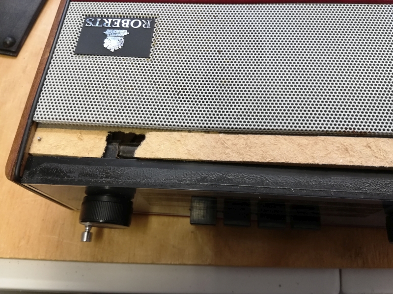
Now, to actually fit the potentiometers to the top plate. The volume pot fitted perfectly – but, of course, I’d measured the previous component for size, so it should have done. The other hole, however, was larger and more awkward because I’d had to extract the tuner knob.

And, as you can see, the hole was half-in and half-out of a step-down in the plastic, completely different to the other side.
3D printing
I measured everything about that step-down, from where the hole was to where the other plastic bits were. I designed the shape in Tinkercad, allowing for cut-outs where they were needed. Here’s the STL should you ever need it. I eventually got the 3D printer to work (after some spaghetti printing) and, to my infinite surprise, it fitted first time! I slathered on the hot glue so that everything would stay in place!
![]()
The buttons arrive
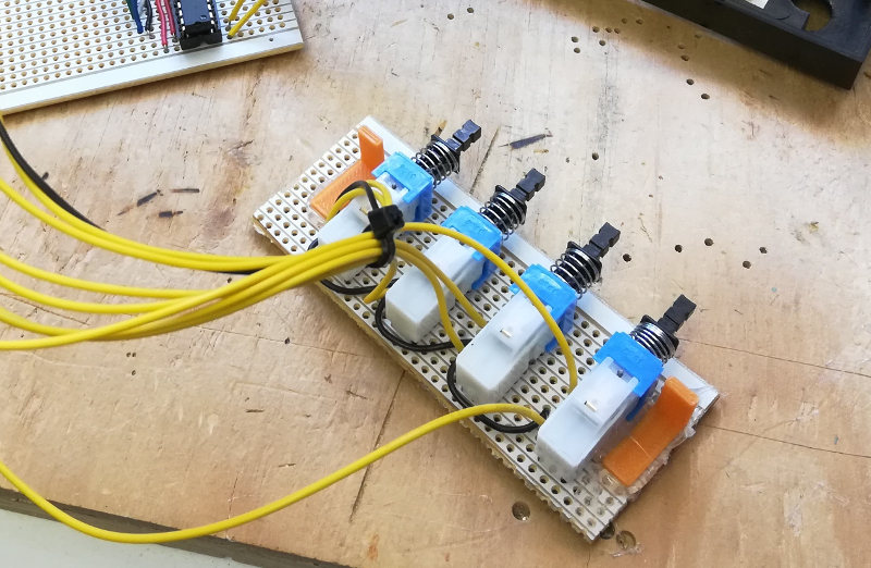
The buttons arrived from RS – yay! I set about working out how to a) mount them and b) affix them to the top plate. I grabbed some stripboard (as the button terminal pins have the same spacing as the stripboard and tested how they would sit:

and here it is in the top plate slot:

Amazingly, the spacing of the buttons turned out to be a perfect fit through the original slots without needing to cut anything away! Now, I could have just piped hot glue into the slot and hoped for the best, but I wanted to mount it better than that. To the 3D printer to design a bracket of sorts – this is what I came up with (STL)! One for each end of the strip board:

A bit of hot glue to hold the brackets in place on the stripboard…
I then glued the strip into the groove and the brackets against the top plate.
The next step was to cut the stripboard housing the MCP3008 to a more manageable size and then to cover the back of both pieces of stripboard with electrical tape to prevent shorts. I then roughly fitted everything into the remains of the case:

Here’s a walk-round of the hardware inside the case:
Everything fit inside the case well, so I first of all made sure the Pi booted, which it did. I knew I wouldn’t be able to plug in a monitor to the Pi once it was screwed down – there just wasn’t enough space – so I set-up wifi while it was booted so I could ssh into it later to do the coding.
I disconnected, screwed down the Pi, slotted the smaller piece of stripboard behind the wiring and then set about re-assembling the case. The nice thing (fortunately) was that the back of the case would be held in by the tightness of the side walls so didn’t need gluing – plus, that would make it easier to remove again if I needed to. I repaired the damaged front with hot glue (as it wouldn’t be seen) and then finished off.

The software
An internet radio needs to be able to access streams of broadcast signals over TCP/IP. The first trick, of course, is to find the stream URLs. No two streaming sites do things the same, so it was a case of searching to see what I could find. I’d already come across this list of BBC network streaming URLs and then I found internet-radio.com and also Shoutcast which had many more. (If you’re going to use internet-radio.com, make sure you can get hold of the .m3u file and that the radio station can be previewed because not all of them are current!) Once you have the m3u file, open it and you will find the URL to play.
Now I had the stream URLs, I needed to find a way to play them. I found a couple of options by eventually went for the python-vlc library having read a Tooling Tuesday post from Les Pounder about the library. To install the necessary software, you will need to do:
sudo apt-get update
sudo apt-get install vlc
sudo pip3 install python-vlc
I wrote some initial software using Python, GPIO Zero and python-vlc over ssh and then tried it out. First button press, BBC Radio 2… lovely. Second button press, BBC Radio 4… lovely. Third button press, BBC Three Counties… lovely. Fourth button press… WHAT ON EARTH IS THAT SOUND!??!?!?!?
For some reason, a huge burst of feedback and static crashed through the speaker. I tried to exit the program but it got… stuck somehow. I pulled the plug on the Pi to stop it, slightly stunned. What had gone wrong? Needless to say, I let optimism get to me and I tried it a few more times (hoping for a different result – stupid!). I tried to figure out why that stream (I forget what it was) which played normally with a simple script wouldn’t work on a button press.
Finally, I tracked it down… I had soldered “button 4 down” to pin 19. Unfortunately, pin 19 is being used by the pHAT Beat for the I2S control/output. Effectively, I had connected that pin to ground by pressing the button, creating a circuit which I2S translated into sound. Doh!
Re-working
There was nothing for it: the radio had to come apart to fix that pin. I also found that the tuning potentiometer was loose, despite being tightened as much as I could with pliers. I first of all de-soldered the pin and re-attached the wire to pin 26 (a safe, unused pin). The back had to come off to get the hot glue gun in to stick the potentiometer down. I let it dry, re-assembled and was delighted that the pot seemed like it was going to stay in place. Now, to try that button!
Success! It all worked! Now to get fancy…
Tuning more stations
I wanted the tuning knob to do something – currently, it didn’t. So, I used GPIO Zero to hook in another channel from the MCP3008. I could read values from the pot, as I was doing with the volume pot, and so I decided to set-up “zones” of 10% of the dial, each would trigger different stations if the fourth button was depressed.
This all worked correctly. I also wanted to create a way to shutdown the Raspberry Pi safely. To start with, I made it shutdown if all four buttons were pressed down together. This was okay, but of course the radio got a bit confused as it was trying to play a station while it was shutting down. I decided, then, to make the volume control an off-switch, to mimic the original potentiometer-with-switch that I’d got rid of. So, with a little help from Twitter, I now have the shutdown routine running if the volume is set to zero for more than 5 seconds (approx).
Speak to me
I wanted some kind of countdown to allow me to abort the shutdown by turning the volume knob again. I thought it would be nice to have the radio “speak to me”.
To start with, I tried out the eSpeak for voice synthesiser (see also the official docs) – but it didn’t have a Python 3 library yet, so I just used os.system to execute it. However, it was very, very robotic. I wanted something better, but didn’t want anything that had to use the Internet and APIs, tokens, licences etc. So, Google Text-to-Speach was ruled out. I then came across Pico TTS (thanks to user jerrm on the Raspberry Pi Forums) which comes with a binary, pico2wave. Again, there was no easy-to-use library for Python 3 that I could find, so os.system had to be pressed into service. There was a problem, though, the standard instructions for installation:
wget -q https://ftp-master.debian.org/keys/release-10.asc -O- | sudo apt-key add -
echo "deb http://deb.debian.org/debian buster non-free" | sudo tee -a /etc/apt/sources.list
sudo apt-get update
sudo apt-get install libttspico-utils
… didn’t work on the Pi Zero because of the CPU’s ARM version. It does work on the Pi 2 and the Pi 3 (and Pi 4 for all I know) but I needed it to work on the Zero, specifically.
However, it is possible to use the Jessie version of the software by doing the following:
wget http://archive. raspberrypi. org/debian/ pool/main/ s/svox/ libttspico- utils_1. 0+git20130326- 3+rpi1_ armhf.deb wget http:// archive. raspberrypi. org/debian/ pool/main/ s/svox/ libttspico0_ 1.0+git20130326 -3+rpi1_ armhf.deb sudo apt-get install -f ./libttspico0_ 1.0+git20130326 -3+rpi1_ armhf.deb ./libttspico- utils_1. 0+git20130326- 3+rpi1_ armhf.deb
pico2wave does text-to-speech fine, but I soon found out you can’t just call it from the command line and have audio come out – instead, it creates a physical .wav file. And will only create .wav files. I wanted to pipe it into audio player aplay… But how…? Luckily, I found a tip that allowed piping to /dev/stdout and that still “sort of” created a .wav file.
First of all, create a symbolic link from a named .wav file to /dev/stdout:
ln -s /dev/stdout stdout.wav
This allows us to pipe the output from pico2wave directly into aplay:
pico2wave -w stdout.wav "Look Dave, I can see you're really upset about this" | aplay
With that worked out, I could then integrate calls to that executable into my Python code.
Demonstration and the code
Here’s a video of the radio as it stands today (13-Jun-2020) (turn up your volume a bit – it’s a bit quiet in places, though the radio is by no means quiet if you turn it up!):
And here’s a link to the code, all on GitHub. Feel free to suggest improvements! 🙂
If you’ve enjoyed this project write-up, feel free to leave a comment! 🙂