
![]() In June 2022, a friend that I know through amdram asked me for some help with his modelling project. First of all, some background: Steff is part of an organisation called Models for Heroes.
In June 2022, a friend that I know through amdram asked me for some help with his modelling project. First of all, some background: Steff is part of an organisation called Models for Heroes.
Models for Heroes is a UK charity that helps ex-Armed Forces personnel with their physical and mental rehabilitation, as well as giving them something fun and engaging to do, via modelling using kits and partial kits.
TL;DR – if you want a summary video, there’s one at the bottom!
The brief
What Steff had in mind was a model of a Lancaster Bomber with movement, light and sound effects. Ah! I thought: a typical Raspberry Pi project. I offered to help with the electronics and soon found myself wondering how to do it. My first thought was to use either a Raspberry Pi Zero or a full-sized Pi as it would need motor control, LED control and also audio output. Then, I got to thinking: can I do this using a Raspberry Pi Pico? It would be cheaper (crucial to this project), it would be more reliable over time (because there would be no OS to get in the way!) and it would challenge me to do something with just a microcontroller. So, I decided to run with the Pico for now – see what it can manage to do.
The parts of the project
To start with, I wanted to make sure that the project was reproduceable. This meant a certain element of plug-and-play, but with some customisation as well. Eventually, I thought, I could do a PCB to host everything together. There is no current solution to wanting to run motors, play sound and also have lots of general outputs for LEDs. I know, right? You’d think that by now someone would have done that! If anyone fancies helping me bring it all together into a PCB, that would be great as I’m not sure my skills run to I2S and H-bridges on the same board!
I knew I needed, therefore, the Pico, a motor driver board and an I2S sound board, as well as something to drive the LEDs. I also wanted a reset button for the Pico (sigh), rather than force the power cable to be pulled-and-pushed if there was a problem with the code hanging.
The Raspberry Pi Pico
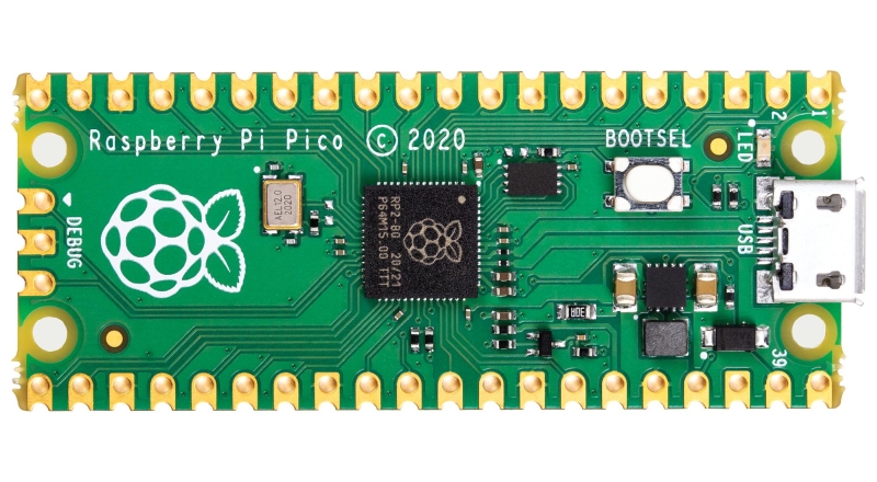
By now, I’m sure everyone and his brother knows about the Pico, but here’s a link just in case. All you really need to know is that it is a microcontroller, rather than a microcomputer, so it’s good for doing one thing in a loop. I worked out a quick list of requirements and realised that I would need to do some kind of multithreading (doing more than one thing at the same time) on the Pico’s two cores to make it work. This ruled out my preferred option, CircuitPython, as that doesn’t have multithreading yet. So, I knew I’d need to do it with Micropython. I’m ever so glad I worked that out at the start!!!
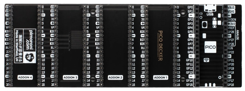
Quad Expander
Of course, most Pico projects using add-on boards just have the add-on plugged directly into the Pico. I had multiple add-ons, so that was a problem. That was until I found the Quad Pico Decker over at Pimoroni. Perfect! One Pico, four expansion headers. I’d only need three (at the moment), so that would do nicely.
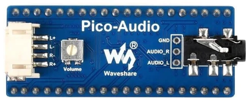
Sound
My first step was to find the sounds I wanted to play. A guy called Des Braban has created/collated a collection of Lancaster Bomber sound effects available over at AVSIM – a library of sound effects for air simulators. Great, it’s freeware. I found start-up and engine-running sound effects within the library, so I’ve adapted and converted those into WAV files that a) won’t take up too much space and b) will be easily playable. I settled on 8000kHz stereo and manipulated and cropped the original samples in Audacity.
Next was to find an I2S sound board that would fit on the Pico Decker. This was an important consideration as there isn’t much space for overhang on those expansion headers. I settled on the Pico Audio from Waveshare and picked one up from The Pi Hut. £13 including speakers? Bargain!
Once that arrived, I looked around for some simple I2S examples and found them on Mike Teachman’s GitHub repository.
Together with the WAV files, I found I could play the sound of the start-up of the engine then segue (a bit bumpily) into the engine-running sample.
Motors

Steff had got hold of a load of tiny, 4mm vibration motors that used to be in mobile phones (pictured above). He wanted me to use them. To start with, I feared that they’d be too fragile for the 3V output of the Pico. But that was okay, I reasoned, if I PWM’d the output in code, I could reduce the load on the motor to a certain extent. First of all, I found the voltage and amperage limits of the motor by using a (brand new) bench power supply. To my delight, I determined that they operated from about 1.7V to about 3.3V. Stall current was about 150mA so, yes, I would need a motor driver to cope with that. I looked around for a motor controller board that would fit on the headers, with no overhang, and came across the SB Components Pico Motor Board which was only £14. The Pi Hut also had it, so I grabbed one.
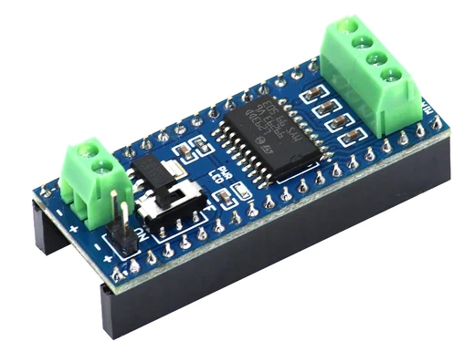
I hooked up the motor, wrote some simple code that PWM’d the output to something “reasonable” and tried it out. The motor span really fast! I lowered the duty cycle further and managed to get it ticking over nicely. Fortunately, it ran from the power to the Pico, although there is a terminal for external power if you need it.
The LEDs
Of course, Steff wanted blinkies! Yay! We like blinkies. But there was no plugin board for the Pico that “just” gave me control over LEDs or gave me standard outputs in the right form factor. That’s okay, I thought, I have a soldering iron. 🙂 The hunt was on for a space-aware prototyping solution. I could easily have done with stripboard, but I knew it would get messy. I came across the Pico Proto from Pimoroni, which I thought was perfect.
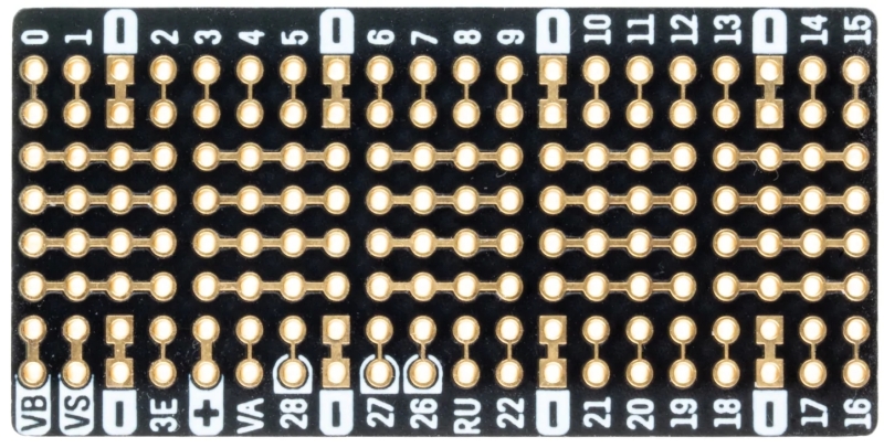
Fortunately, my good friends Tim Richardson and David Booth both had a spare, so I popped over to Tim’s and picked it up. I started soldering. Here are some of the lessons I learned…
- Solder the female headers on first as otherwise you might find yourself with blobs or overhanging soldering that mean you can’t get them on afterwards.
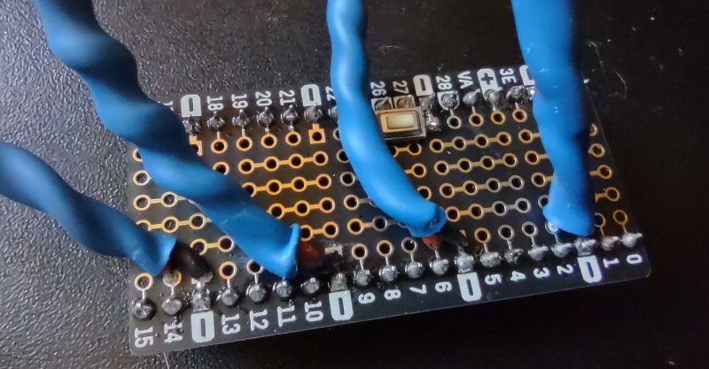
- Use a surface-mount reset button if you want one. This lowers the amount of solder on the board, plus the legs of most through-hole buttons are too thick for the Proto. Fortunately, I head a surface-mount button that was ideal and fitted exactly between RU (the ‘Run’ pin) and the ground pin above GP27.
- Put some heat-wrap over your joints, and over your LED legs. Heat wrap everywhere. BUT be aware that LEDs (particularly the 3mm ones I was using) are sensitive to heat! So, if you’re using a heatgun to make the heat-wrap shrink, be aware that too much heat on the legs or on the LED itself will stop the LED from working. I learned this the hard way! Oh, for God’s sake remember to put the heat-wrap on the wires before soldering on the components… That too, was learned the hard way.
- You need very little solder on the Proto. Too much and you start bridging connections and blobbing where you don’t want blobs.
A lot of soldering later, and a couple of failed attempts later, and I had my LED board.
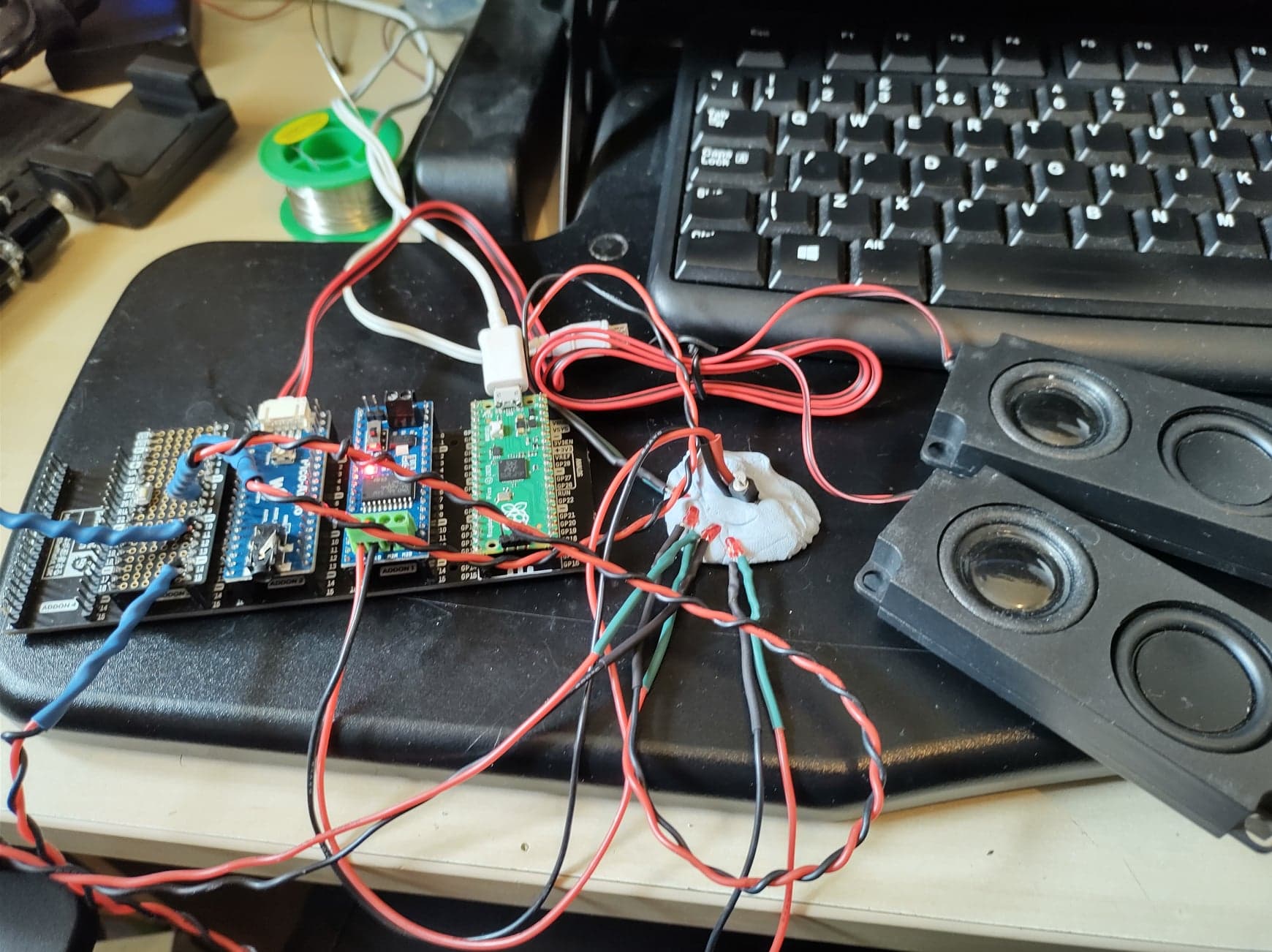
The test bed
After a lot of testing the individual parts, I brought them all together and had a test bed (with BluTack to stabilise the LEDs and the motor).
My code
My code is all on GitHub. On the Pico, you need, at a minimum, motor.py, main.py and the two .wav files. The other files are test scripts I used for proof-of-concept which may be of interest.
Demo video
Here goes, I thought, I’ll do a quick video walk-around of the project so you can see it working. Fortunately, I captured this before I managed to snap one of the legs of my sample motor. Argh! Here we are, anyway: