Seven Segments of Pi – All our monitors are VGA! (Part 4)

FromJamboreeToCamJam_Banner

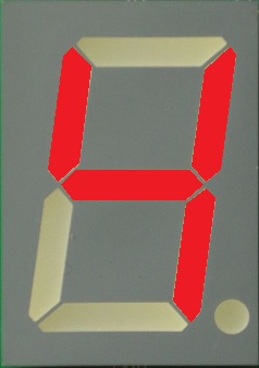
Last week I described how in June 2012 pupils had modified some Python Software on the Raspberry Pi to make the attached Seven Segment Display count to …

Seven_Segments_of_Pi_Assy_LED_Displaying_4

…and I realised I had something which answered the pupil’s question…

but_what_does_it_do

“Yes! …but what does it do!?”

 …something I could use for Raspberry Pi Workshops in schools!

I still only had one Raspberry Pi, but I had plans to buy at least 2 more. With 3 Raspberry Pi’s I could probably run Workshops with up to 9 pupils. But whilst I could buy 3 Raspberry Pi’s, I didn’t have 3 Keyboards, Mice and Monitors.

Keyboards and Mice were easy. Most schools had plenty of USB Keyboards and Mice for me to borrow, but as soon as the teachers realised the only usable video output connector on the Raspberry Pi was HDMI…

 HDMI 
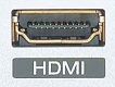
…I got the immediate response…

VGA

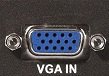
”Yes! …but all our monitors are VGA!”

…and there was no way schools were going to buy loads of HDMI TV’s just to run a few Raspberry Pi Workshops!

 This seemed to be a bit of a road-block! I might be able to borrow 2 or 3 HDMI TV’s to run some workshops but it looked like a big barrier to the general acceptance of Raspberry Pi’s in schools!

A little bit of research was required! I had never taken much notice of how my PC attached to its monitor. I was familiar with the VGA input, but I found my PC’s monitor also had a DVI input…

DVI

…and that HDMI and DVI signals were compatible. So I attached my Raspberry Pi to the DVI input on my Monitor with a simple HDMI-to-DVI Cable…
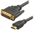
HDMI-to-DVI

…and it worked!

I went back into schools to see if they too had DVI as well as VGA inputs on their monitors. Unfortunately most did not! “When we bought our PC’s, we had to buy the lowest cost monitors, and they were the VGA-only ones!” was the usual answer.

At one school however the teacher said “I’ve got an HDMI-to-VGA Adapter box in the car” It was worth a go. It was a bit cumbersome since it had to be mains powered, but it prompted me to search for other HDMI-to-VGA Adapters.

Searching on Amazon I found this self-powered adapter made in the far-east by “Neewer”**…

HDMI-to-VGA

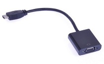
…with a user comment saying they had successfully made it work with their Raspberry Pi by modifying the Raspberry Pi’s “config.txt” file. It was only £12.99 so I ordered one.

It worked! I now knew I could run Raspberry Pi Workshops in schools. But what is more, I could tell schools…

“You don’t need HDMI Monitors to use Raspberry Pi’s in schools!”

**The use of the original “Neewer” Adapters was not entirely trouble free as I will describe in a later blog entitled “Doh! There’s no sound!” but their current version may be OK. I have also tested 3 other HDMI-to-VGA Adapters and all three have aspects I think could be better so I have asked for clarification from the manufacturers. Hopefully by the end of this series of Blogs I can recommend at least one HDMI-to-VGA Adapter!

Next week I will look at how I developed a more comprehensive set of Software Challenges (and ordered a couple more Raspberry Pi’s) so I could run Raspberry Pi Workshops in Schools in a Blog entitled…

”What can you do with just Seven Segments?”

If you are interested in learning more about the Seven Segments of Pi visit my Web Site www.SevenSegmentsOfPi.com or watch the “Seven Segments of Pi” YouTube Video. You can also watch Carrie Anne Philbin playing “Figure Eight My Pi” at the CamJam, courtesy of Alex at RasPi TV.

NevilHuntPhoto_QuarterSize

Nevil Hunt

Innovations in Education


Pi Co-op – #RaspberryPi / #Arduino add-on board review & a lie detector

The Pi Co-op is an expansion board that plugs straight onto the GPIO header and gives you immediate access to an Atmega328p microcontroller chip. Essentially, it gives you an onboard Arduino! It’s also pre-soldered which means you don’t need to know how to solder in order to get going.

Alan over at Dawn Robotics sent me one of these boards in the post and after a few days I finally found time to use it. This is a bit of a rambling review because of what I use to test it out, by the way.

Here’s a list of the features:

  • Atmega328p microcontroller preprogrammed with the Arduino Uno bootloader.
  • 10bit 8 channel Analog to Digital Converter (ADC).
  • Can be programmed directly from the Raspberry Pi using the free Arduino IDE.
  • Level shifted UART for fast communication between the Pi and Pi Co-op at a baud rate of up to 115200bps.
  • Atmega328p pins broken out to female headers for easy prototyping, just plug in wires or connect to a breadboard.
  • Power line incorporates the same type of fuse used on the Pi MicroUSB connector (700mA hold current, 1100mA trip current). This allows the Pi to be safely powered from an external 5V supply attached to the Pi Co-op.
  • Standard spacing of 2.54mm between all headers allows expansion boards to be created easily using copper stripboards.

If you don’t understand any of the next part of this review because you are not familiar with Arduinos and microcontrollers, suffice to say this is a brilliant way of getting started with analog (i.e. non-digital) sensors.

It’s fair to say that this is the easiest way I’ve found to use an Arduino with the Pi. Dawn Robotics give you a set of instructions to get up and running (which involves installing a fair bit of software) and soon I had the traditional ‘blink’ example script running. (For those of you who don’t know what this is – most Arduinos have an LED onboard connected to pin 13. The ‘blink’ script essentially just makes the LED flash. It’s the Arduino equivalent of ‘Hello World’). I should say at this point that the instructions given are simple, clear and they do work. All of this took me about 3/4 of an hour, most of which was spent waiting for software to install. This is acceptable because after you’ve got Git and some Python bits and pieces installed, you’re going to be controlling the Arduino from Python on the Pi anyway. Part of the software install puts something called Firmata onto the Arduino chip. This allows you to communicate with, and control, the chip via the serial line.

The next thing I did was to plug in an analog sensor to try and get some readings.  For this, I chose a GSR (Galvanic Skin Response) sensor that I’d got from Phenoptix. The GSR sensor measures the electrical conductiveness of your skin from two metal finger pads. They use GSR sensors in lie detectors because when you sweat your skin becomes more conductive – the same goes for any strong emotional response. They’re also used in sleep studies to record dream states. Anyway! So, after a bit of fiddling about with various wires, I plugged the 5V and Ground lines in and then plugged the signal line into analog 0. I then created the following script on the Pi:

import time

from PyMata.pymata import PyMata

# Sensor connected to analog pin 0
SENSOR=0

# Create an instance of PyMata.
SERIAL_PORT = "/dev/ttyS0"
firmata = PyMata( SERIAL_PORT, max_wait_time=5 )

# initialize the digital pin as an output.
firmata.set_pin_mode( SENSOR, firmata.INPUT, firmata.ANALOG )

time.sleep(1)

try:
  # run in a loop over and over again forever:
  while True:

    reading = firmata.analog_read(SENSOR)
    print (reading)
    time.sleep( 0.05 ) # wait for a second

except KeyboardInterrupt:
  # Catch exception raised by using Ctrl+C to quit
  pass

# close the interface down cleanly
firmata.close()

To start with I received readings in the mid-500s and then I put the finger sensors on and the readings dropped to the mid-400s. I tried it out on a couple of people, with varying sweaty hands and sweatier the hands the lower the reading. I also tried touching the metal pads to each other and got a reading of zero. I deduced that the more heightened the emotional response, and therefore the more sweaty the hands, the lower the reading. If you’re using it as a lie detector, you should ask some control questions to begin with to establish a ‘normal’ level and then move on to more emotional questions, or questions that might elicit a lie! You should find that the readings reduce during lies.

Anyway, back to the Pi Co-op. It took me all of 30 minutes to connect the GSR up and write the script – it was really that simple to go from the blink example to reading an analog sensors.

So, to sum up. It’s a very effective, very simple way of adding inputs, especially analog inputs, to your Pi. At under £20 delivered, it’s also cheaper than most of the alternatives out there. There are a few downsides, however, which in an effort to be balanced, I’ll tell you about. The Co-op doesn’t come with a lot of documentation, just enough to get you going (and it certainly beats the Gertduino for ease-of-reading-and-understanding). There are example scripts included with the code you download/install, but they aren’t specific to the Co-op so it can be a bit confusing. The Co-op also doesn’t come with an extended GPIO header which means that you can’t use the GPIO pins for anything else. This is a shame, really, as the only pins that are used are the TX/RX pins. By including an extended GPIO header, this would have increased the usability tremendously. The other minus note is that the broken out pins don’t correspond to the form factor of Arduino shields, but then again there might be compatibility issues with that and this is offset by making the Co-op smaller.

In terms of a score, I’ll have to rate it a 9/10 (it loses one point for hogging the GPIO but I can’t bring myself to dock another point for documentation as there is enough here to get you going and I’m sure the community can provide more examples as time goes by.)

You can buy a Co-op for £16.99 (+£2 delivery) from Dawn Robotics.

Oh, here’s a pretty good video about the Co-op!

RasPi.TV launches new product range for the #RaspberryPi

Alex Eames, over at RasPi.TV, has today launched three products for the Raspberry Pi market under the RasPiO label. They are:

  • A port labels board (similar to other ones but nicely done) – it slips over the top of your GPIO pins to act as a handy reference.
  • The RasPiO Breakout (which breaks out the GPIO pins to both male and female headers)
  • The RasPiO Breakout Pro (which breaks out the GPIO to both male and female headers but protects the input/outputs with resistors to prevent you doing anything silly to blow up your Pi)

These look very good quality boards and Alex has clearly done a great job on designing them and bringing them to market.

He’s selling them through Cyntech and CPC. Prices on Cyntech are currently:

I can recommend these boards (I’ve got early versions of the Breakout and the port labels board and they really are cute, well designed, little boards) and the prices aren’t too bad either if it’s ‘just what you want’. Certainly takes the headache out of prototyping if you just want to stick a few things into the GPIO.

Alex has also done a video introducing the boards which you can see below: