Due to the unfortunate closure of the Milton Keynes Raspberry Jam; the forum including details of this project had to be removed which meant the build history would have been lost forever. However luckily for me, Mike being a lover of all things Raspberry Pi put on his suit of shining armour came to rescue, so here we are!
– Daniel
History

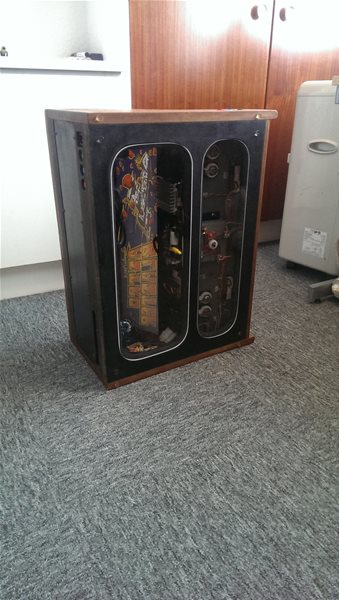
AstroBlaster after it was rescued in the 1990’s
Back in the early 90’s, with the help of some friends I rescued an original 1980 AstroBlaster arcade machine from a barn auction. Unfortunately it was in such bad shape that whilst we did manage to get it home, the cabinet didn’t survive long (it was completely rotten) and someone had already replaced the electronics with a more modern game called “Mr Do!”. I did however keep the control panel and the marquee (the bit that lights up at the top) which were both original and complete with breathtaking artwork, thinking one day I might do something with them….
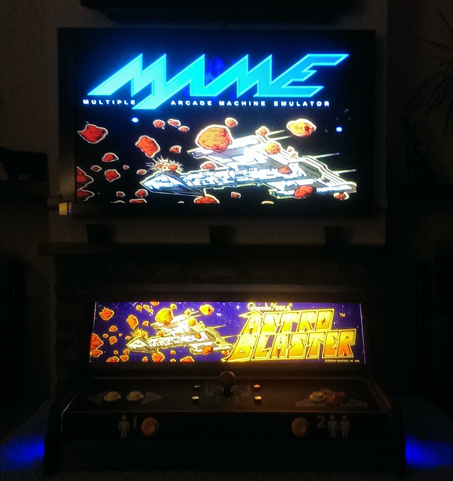
They sat in various lofts over the years as I moved from house to house, still not really knowing what to do with them – until thanks to the MAME project and some dumps of the original 1970’s ROM’s for the game, I decided to build an emulator using the Raspberry Pi!
Due to the way MAME emulation works, its actually pretty realistic and is almost indistinguishable from the real thing (the feel of retro arcade games are totally different to modern games) so I decided to dig the old bits out from the loft (which had been there for almost 20 years!) and start the restoration. After much thinking (and unfortunately giving in to practicality) I decided not to build a full size cabinet (as they are HUGE and can’t be taken to Raspberry Jams!) but instead build something could be put on a table and hooked up to a TV with HDMI.
The Marquee
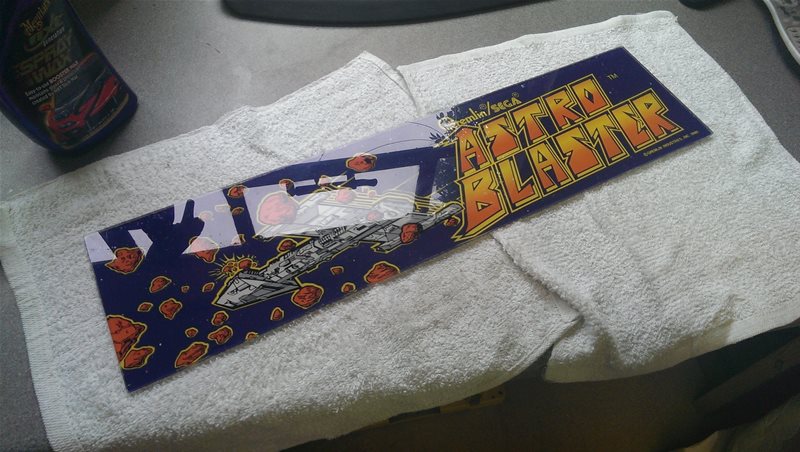
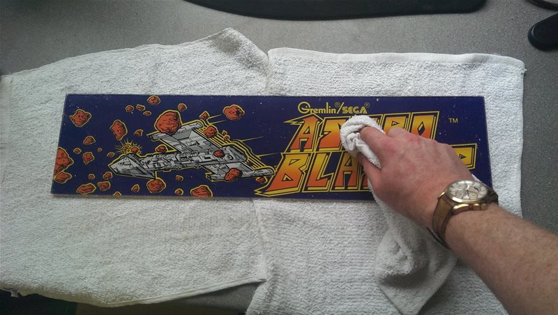
I started the project by fixing up the marquee which is the backlit perspex panel mounted across the top of arcade cabinets. I knew this would be an important feature of the build and as such if I couldn’t clean it up, it may not be worth continuing. It was heavily scratched and covered in paint (and some other things I’m not even sure about) but at least it was complete. After lots of cleaning compounds, some cutting polish and elbow grease I was happy with the result and had a good start to my project. This gave me the motivation to continue.
The finished result!
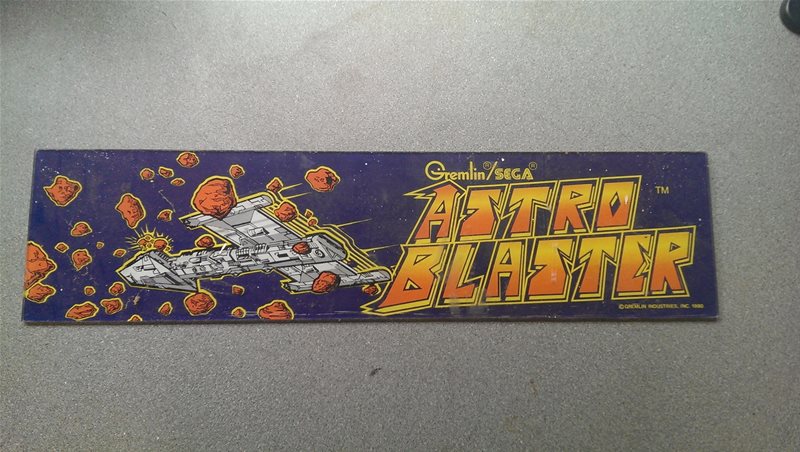
Its original state
Trying every compound known to man to get it shiny again!
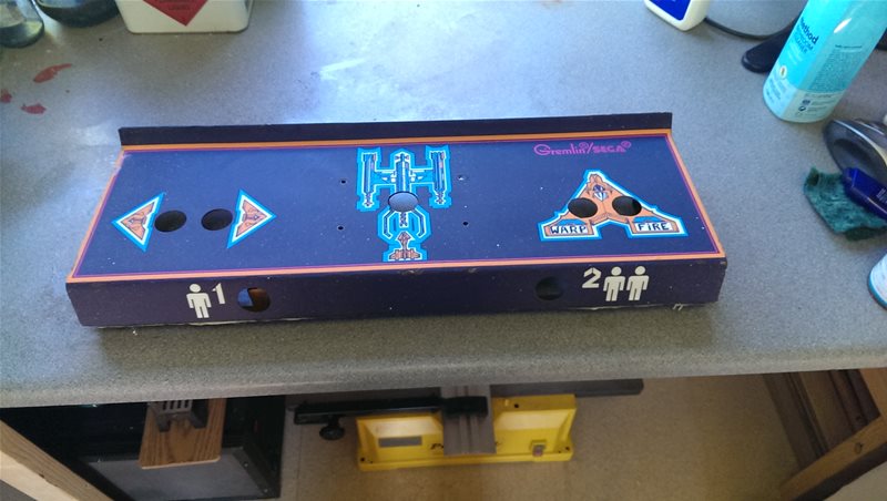
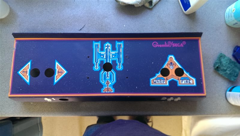
The Control Panel
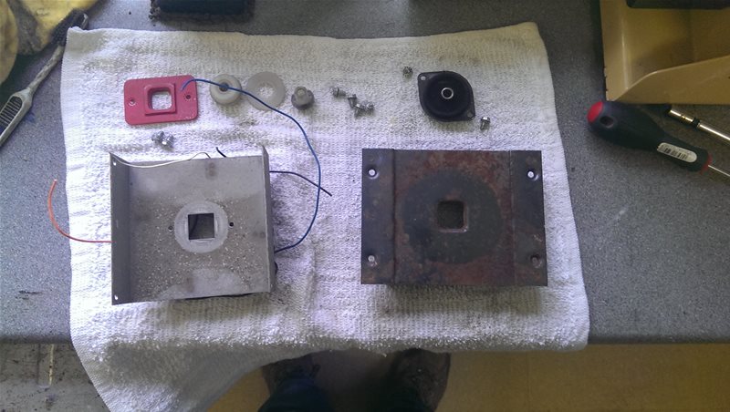
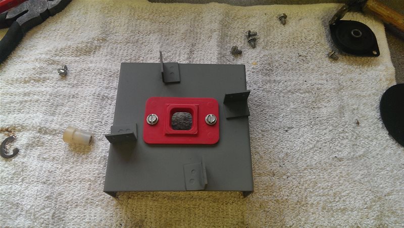
Next was the control panel, it was in a really bad state. The wiring was a mess, the controls were worn and melted (probably from cigarettes) and it was heavily rusted. It was depressing to say the least but I’d set myself the challenge I pulled out the tools and started work.
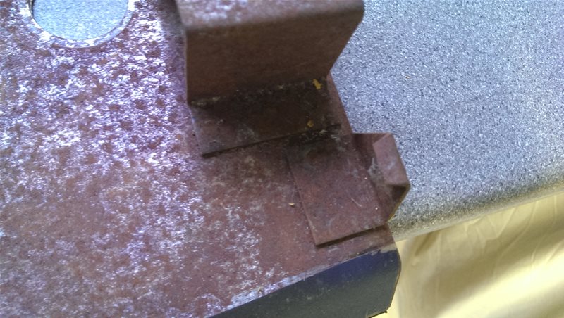
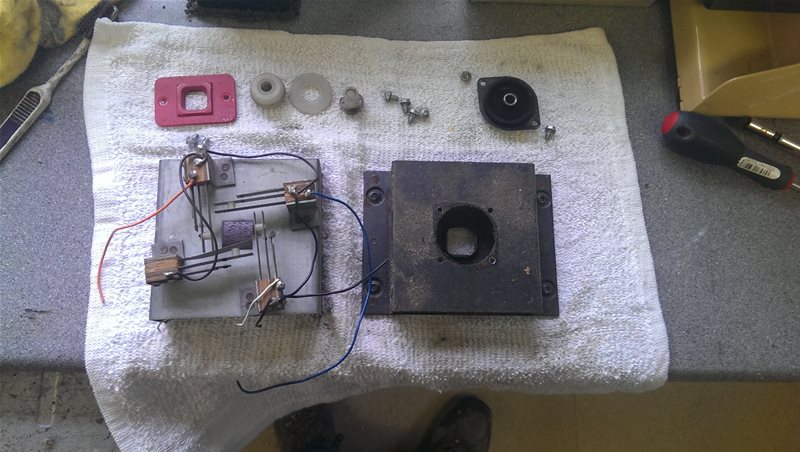
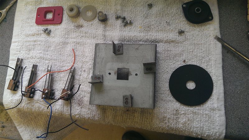
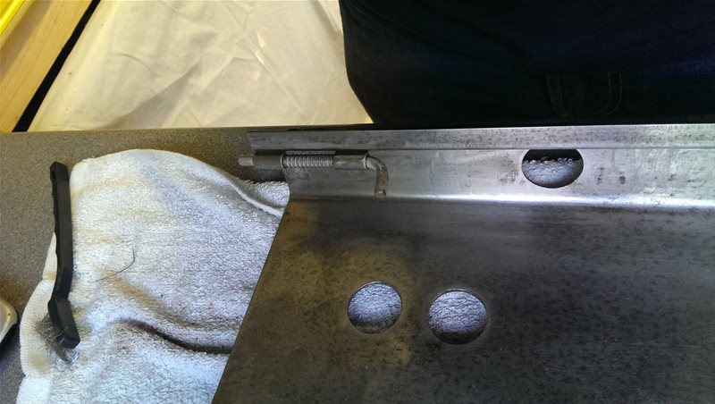
The hooks which held it in place
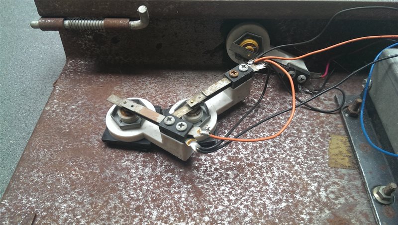
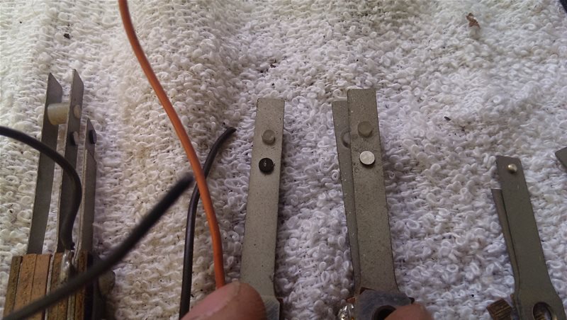
The push button contacts
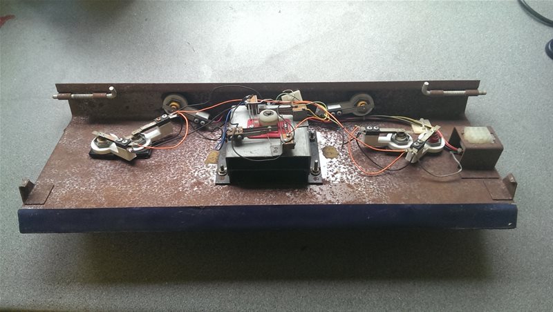
An overview of the underneath
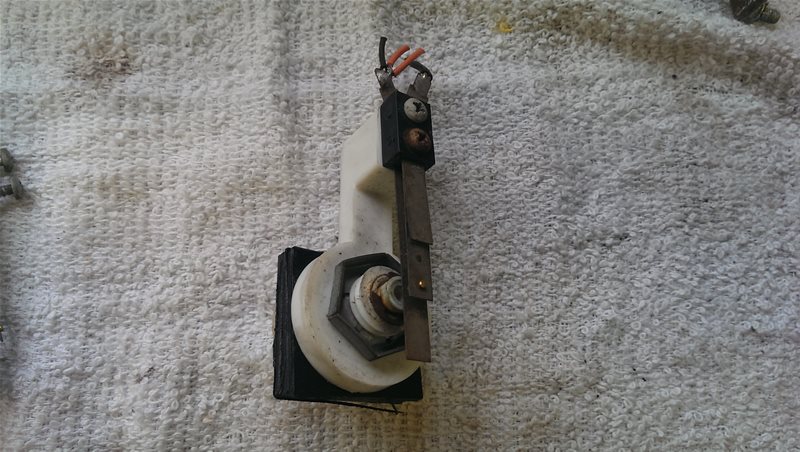
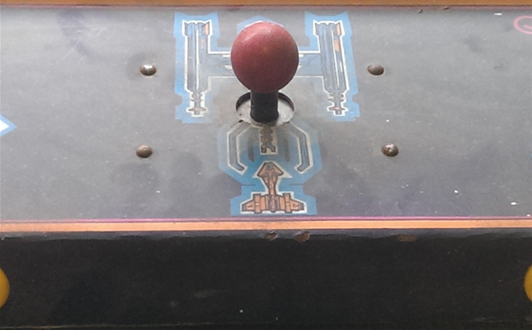
The Joystick
After checking the control panel I decided to start with the joystick, it was key to the project after all. I could have just bought a new one but I wanted the authentic “non-microswitch” feel of the original, and after a struggle I managed to remove it from the rusty panel. The joystick like the panel was heavily rusted in but almost complete and worthwhile repairing.
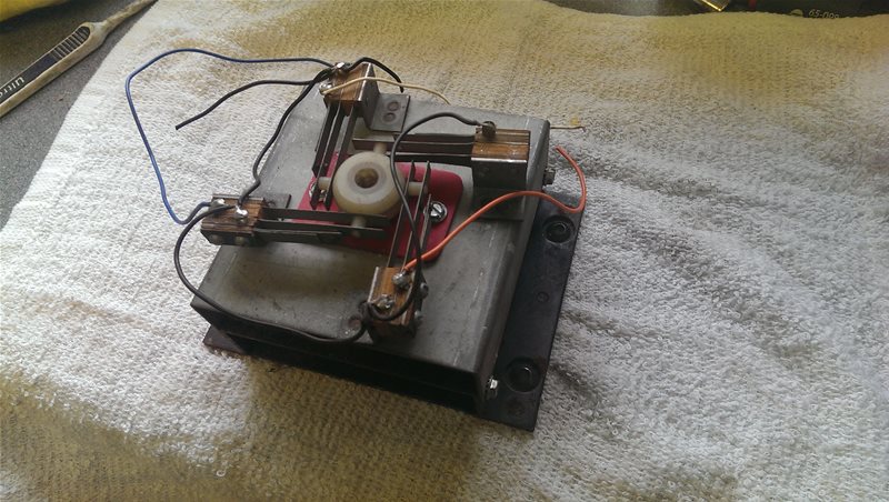
In its original state
The rust on the underside
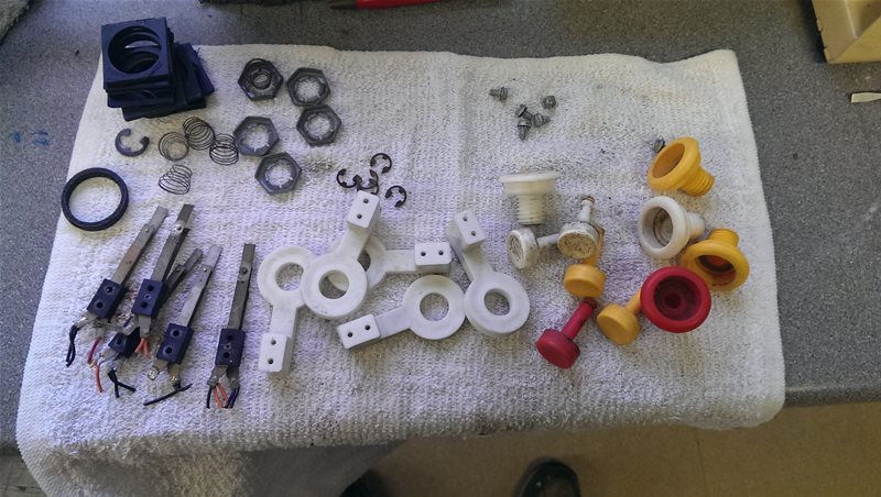
Stripping down piece by piece
Fully dismantled
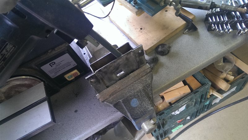
Getting into the nooks and crannies with a powerfile
Getting rid of rust the old fashioned way, elbow grease!
Rust removed!
A coat of Zinc primer to keep it that way!
Contact Cleaning, Repairs and Reassembly
The next task was to get it to a state where it would actually work, so I had to do some contact cleaning and minor repairs. After that I removed years of grime from the knob, waited for the paint to dry and reassembled the joystick..
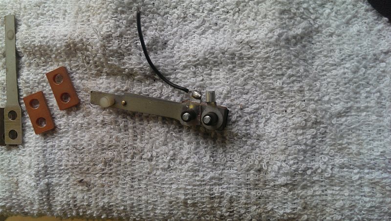
Fixing a broken terminal with a ring connector
Disassembly and cleaning with a fibreglass brush
Left – Original
Right – Cleaned
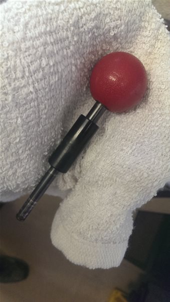
Cleaning the knob
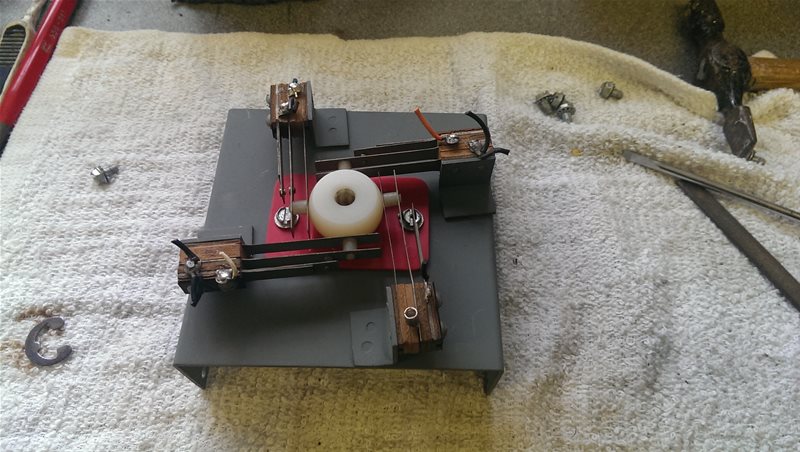
Mounting the switches
Reassembly
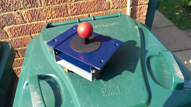
The finished product!
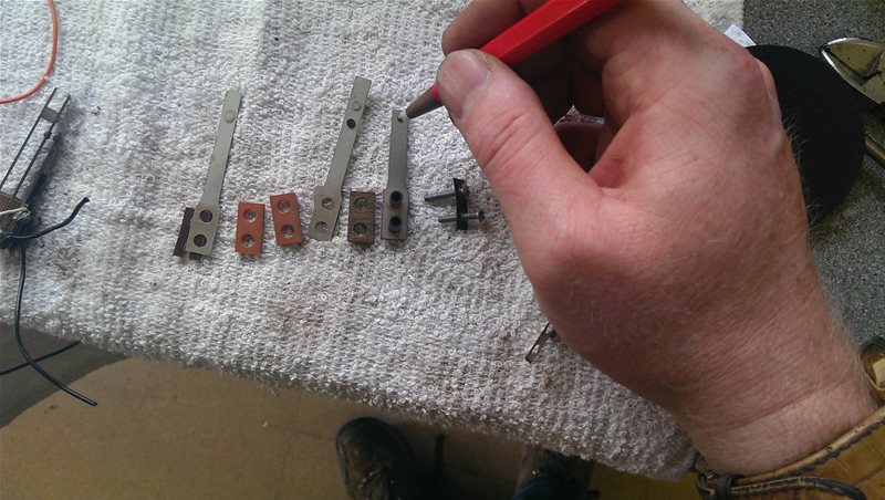
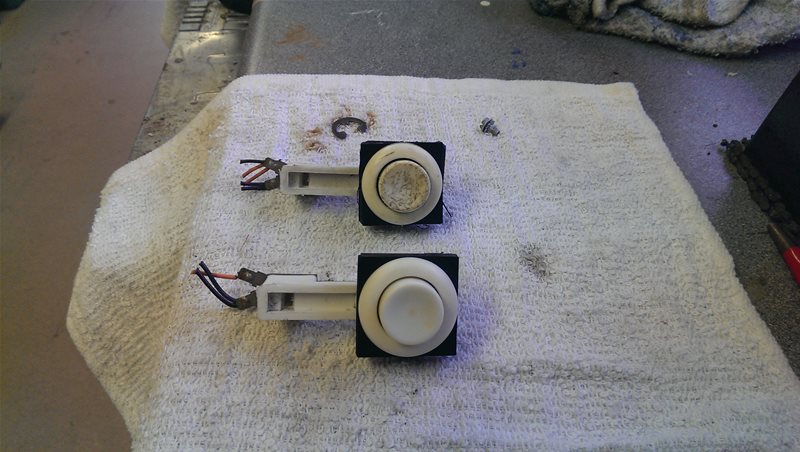
The Buttons
Arggg the buttons, they were ‘orrible! Again I could have bought new, but I had to go and want authentic didn’t I!
After spending a long time considering my options I decided the only way to fix them was going to be to put them on a lathe and try to make them smooth again. I started with some rough sandpaper and worked my way down to the smooth stuff. It was fun for the first couple of buttons but by the time I got to the 6th it was starting to get a little dull 🙁
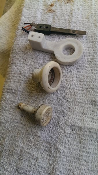
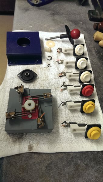
Dissasembly
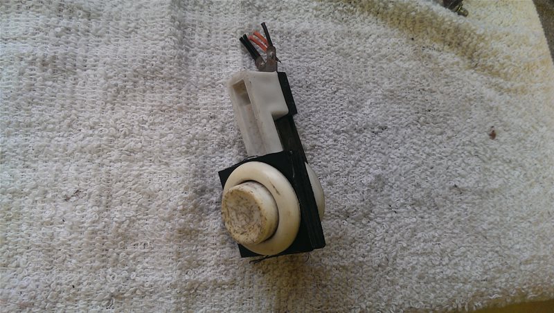
What a state!
Bad contacts
Top – Before
Bottom – After
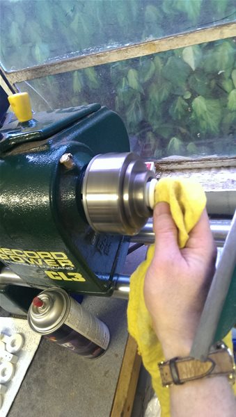
A final polish
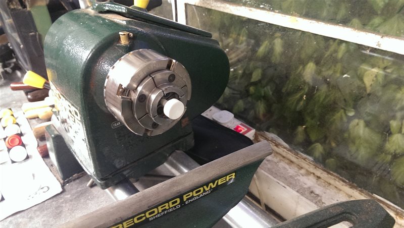
Using a lathe to smooth them up
One down, 5 to go 🙁
At times I wondered if it was possible, turns out it was!
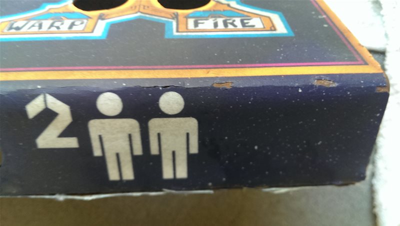
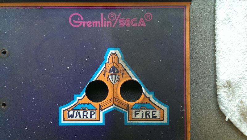
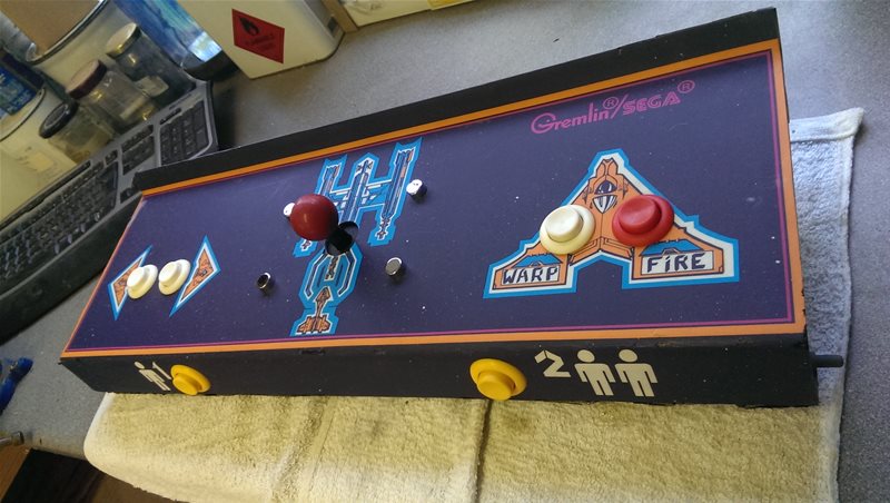
The Control Panel Metalwork / Vinyl
Next to tackle was that filthy, rusty and chipped panel 🙁 It was not good news…. the vinyl was splitting which was a big problem but it was irreplaceable so had to be dealt with as best possible…
The first stage was to clean up the graphics as best I could and after lots of experimentation I finally found a way to cut through the decades of dirt, sugar soap and lots and lots of scrubbing! After hours of labour the brilliance of the artwork started shining through and gave me the motivation to continue the job….
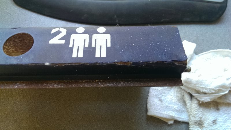
Even more splitting vinyl!
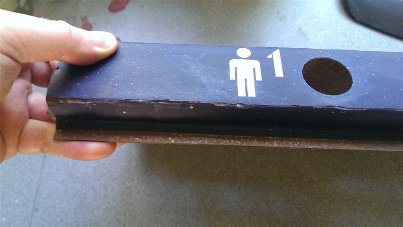
The splitting vinyl
More splitting vinyl 🙁
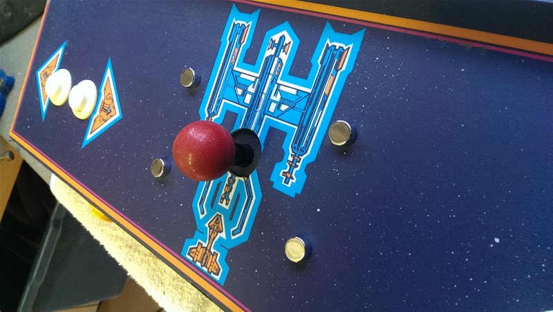
The dirt around the joystick
Looking good!
Warp cleaned
Fire still with grime
All scrubbed up!
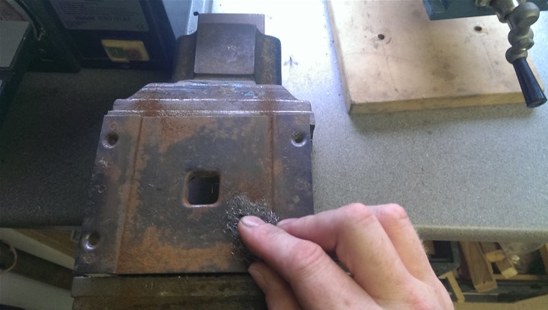
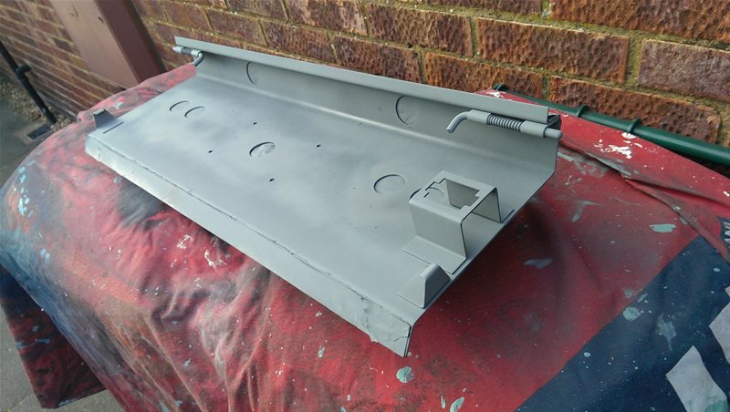
Tackling The Rust
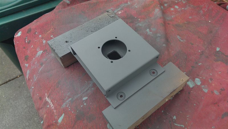
The next stage was back to bare metal with the panel (more rust – groan!) followed by a coat of Zinc to protect it (making sure to cover the edges without getting the vinyl!)
The best I could do with the vinyl holes/splits was to use Kurust to get it back to metal, then “Hammerite straight to rust” to stop it getting any worse followed by some superglue. I was dubious at first whether this would be good enough but seems to be fairly sturdy, at least on the front edge. The bottom edge would need to be protected though. (This is of course when you discover super glue does indeed bond skin in seconds but seems to take ages to bond anything else!)
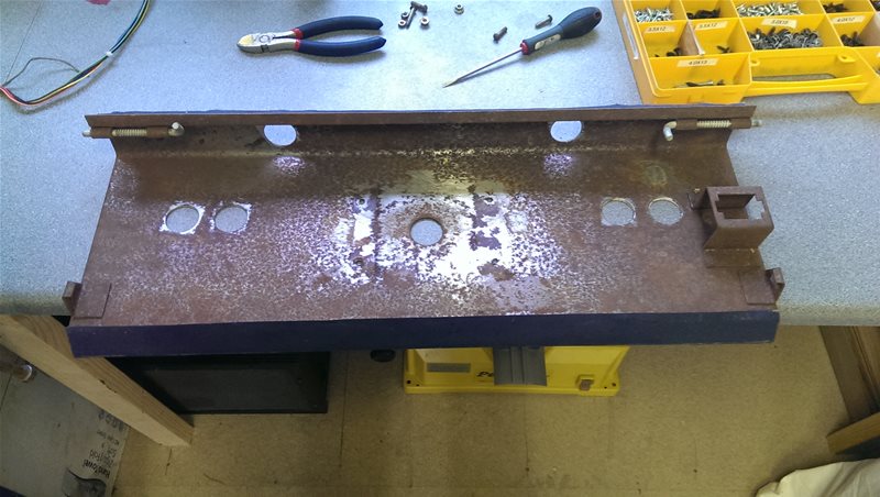
Original rusty state after everything removed
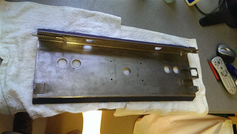
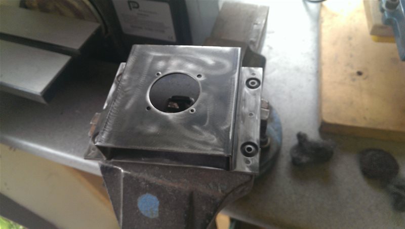
All cleaned up!
Making sure to get every little bit!
Being sure to cover the left edge without getting paint on the vinyl
The bottom edge after painting
The coated panel
Repairing the split vinyl
Panel Reassembly and Wiring
Reassembly was actually much more difficult than it looks, I wont go into too much detail but needless to say there was plenty of hollering when things went wrong 🙂
Since it was originally built to withstand the abuse of hundreds of teenagers it was essentially an industrial specification control panel. As such the joystick was held in with some reasonably substantial chrome dome headed M5 bolts (which were now rusted to oblivion of course). I wanted to keep the original look but unfortunately I figured the chances of finding chrome domed M5 bolts in 2013 was going to be somewhat challenging!
So basically I opted for what I thought was the easier solution, normal bolts in chrome mirror fixing caps. Only here’s where it gets tough, the mirror caps they sell in DIY shops are designed to have tiny little screws in them not M5 bolts. As you can imagine fitting the bolts inside the caps involved hours on the grinder reducing bolt heads down! I think the end result was worth it though, they really blinged it up….
Next was the wiring. I was originally just going to use multi-core telecom cable but I decided that since I’d put so much effort into keeping the rest of it original that would be heresy, so I went for a more traditional “valve wiring style” approach. It took a little longer but again I think it was worth it as it now looks as it would have done originally.
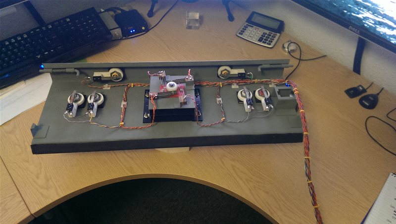
Keeping the wiring traditional
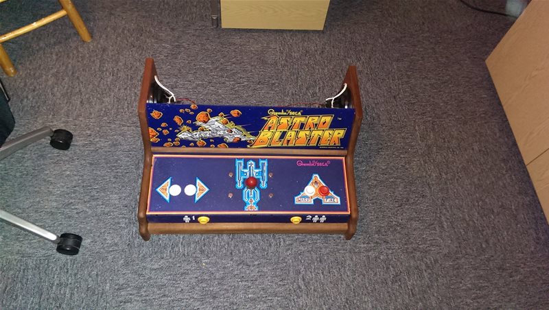
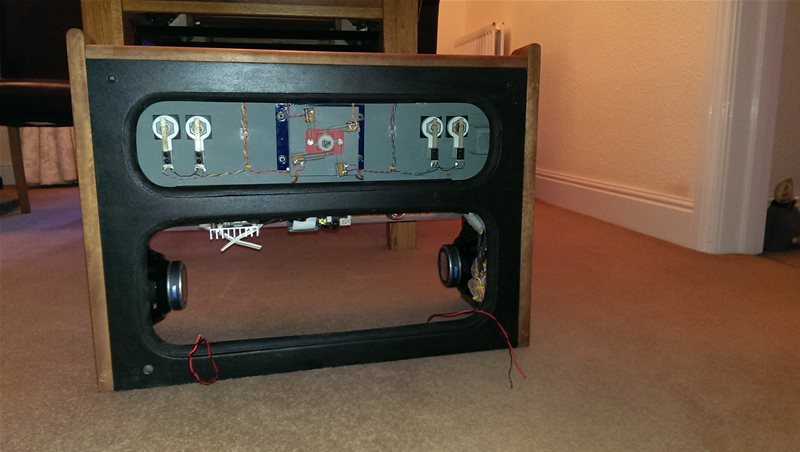
Overview of the restored panel
Close up showing the chrome mirror fixing caps
The GPIO Interface Board
First job in building the GPIO interface for the control panel was to get a connector on the end of the harness. To save money I used whatever I had lying around. Here you can see me half way through splicing on an old PC motherboard power connector and two four pin hard disk power connectors. The motherboard connector will plug into the interface board and the two 4 pin connectors will go to the left and right auxiliary controls which I will tell you about shortly.
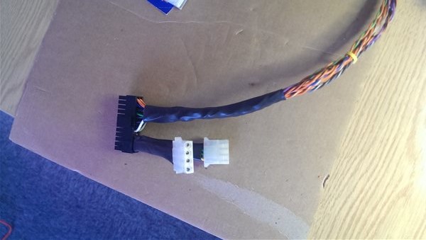
Making use of old PC power connectors
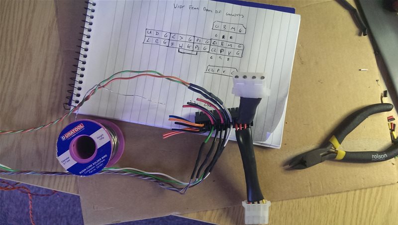
Lots of heat shrink
Next was the GPIO interface board itself, which is of a pulldown design (where the GPIO’s normally sit at ground until you press a button and they then go high). In total there’s 16 control inputs using almost all of the available 17 GPIO’s, every input having its own pull-down and protection resistor (in total there’s almost 40 resistors). In the end I actually wired up all 17 leaving one input spare for maybe adding a charity coin slot at a later date 😉
The two transistors you see on the end are required because two of the GPIO’s are normally used for I2C and thus the Pi has integral pull up resistors. Since I wanted my GPIO’s to be normally low and my control buttons were push to make, I had to invert the logic on those two channels with transistors.

The nightmare which is stipping and soldering ribbon cable!
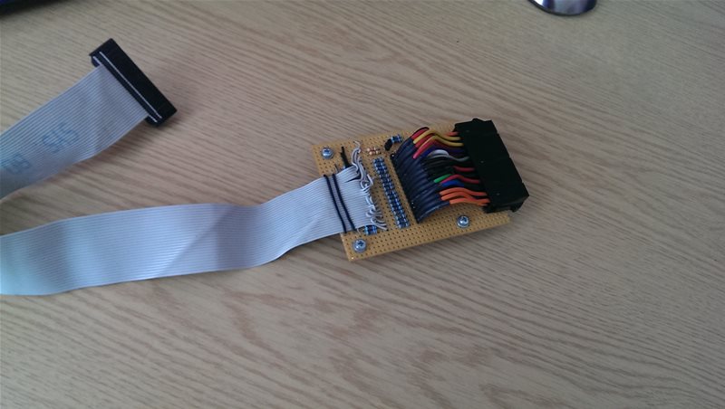
Yup you guessed it, thats an old floppy drive cable 🙂
As it turned out doing it the pull-down instead of the pull-up way was actually a bit of a mistake as it made everything a lot harder. As well as the transistor circuit I had other issues….
Firstly the Pi wouldn’t boot from cold when the board was hooked up, I basically had to boot up the Pi and connect the board afterwards. Some investigation showed that this is because someone decided to put a little known “feature” on the Raspberry Pi which causes it to go into “Safe Mode” when you pull Pin 5 low at boot time. This seems a little silly to me for a number of reasons, not least because it doesn’t actually work (it causes the Pi to lock up, well my Pi at least) but mainly because why would you need a safe mode system enabled by default on a device where you can simply pull out the SD card and read the contents? Luckily I figured out how to disable it by adding a setting in the boot config file, so all was good.
Secondly I had to modify the retrogame GPIO driver which takes the GPIO inputs and emulates a HUD keyboard. By default the driver enables the Pi’s internal pullup resistors (for people who don’t wish to use real resistors) and uses inverted the logic so people can use controllers which ground the GPIO pins instead of taking them high. However after teaching myself a bit of C programming (first time in decades!) I managed to modify the driver code to put the logic the way round I needed, and I also removed the pullup resistor code so it wouldn’t cause problems with my external pulldown resistors. (By the way the internal pullup resistors appear to be around 50k, which in my opinion isn’t really low enough, if you do use the driver as it is it might be an idea to supplement them with external pull-ups as well.)
If I ever did it again I would simply do the inverted logic (pull-up method) to save myself a lot of hassle with the Pi and the driver, hindsight is a great thing huh! But overall what I did works, so I’m happy 🙂
Other issues I had were with the Pi using some of the GPIO pins for other functions such as RS232 (which I needed to disable) and performance issues with MAME (latency is not good when playing games!). I resolved a lot of the performance issues by using Mame4All instead of full blown MAME (ironically an optimised version of Mame4All is now in the Pi Store so anyone doing anything similar has an easy life!)
The Front Trim
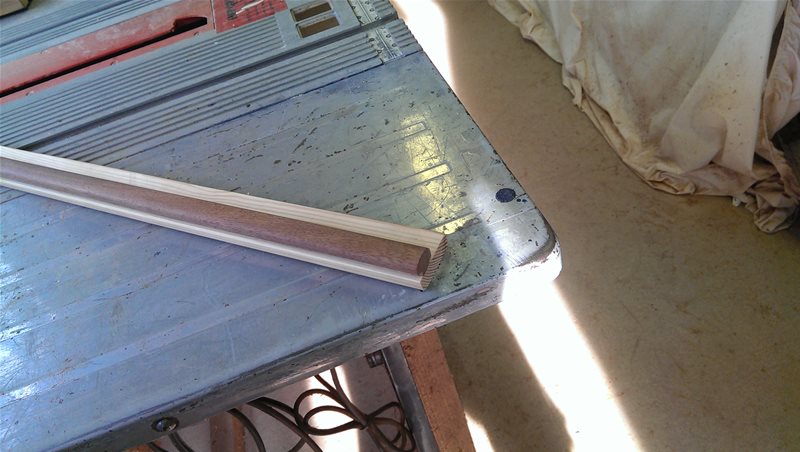
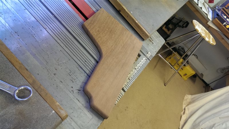
First part of the woodwork build was the base (which I cut out of a sheet of inch thick MDF) and the front trim which I made out of a piece of reclaimed mahogany which I had previously plained smooth.
The front trim performs 3 tasks:
1. It supports the weight of the control panel and anybody leaning on it, whilst holding it in place.
2. It protects and covers the fragile and split vinyl along the front edge.
3. It gives a cosmetically pleasing front to the machine
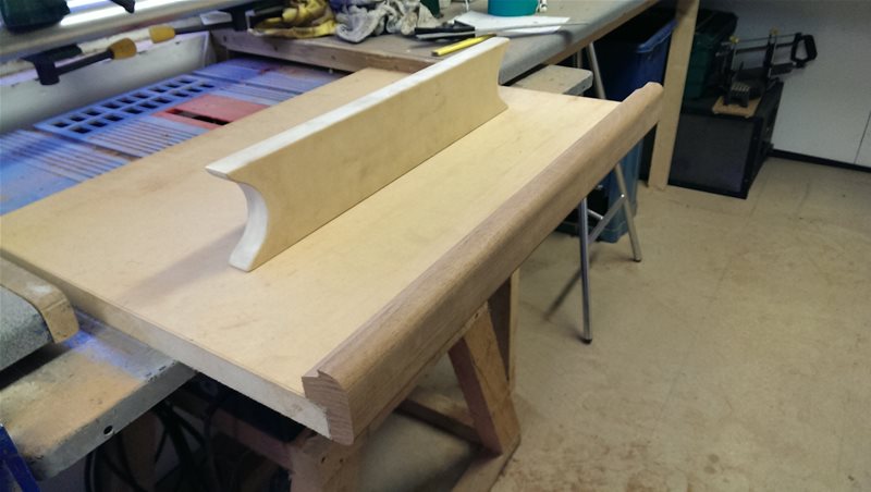
Mocking it all up with the base and rear support
Measuring up the template and matching with the mahogany offcut
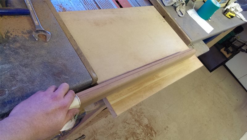
Smoothing off with some sandpaper after routering
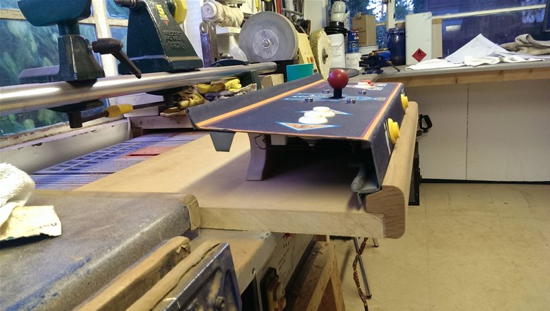
All together with the control panel
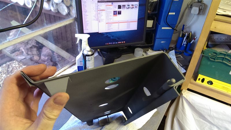
The Base
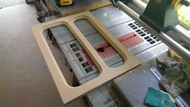
Next was to was make the holes for the perspex cut-out windows in the base…
I did this by cutting 8 circular holes with a hole cutter which I then joined with straight lines to make rectangles with rounded corners. (… I say straight lines, as anyone who’s ever used an electric jigsaw knows, they rarely cut anything straight, especially in inch thick MDF. You can almost guarantee that even if you follow the line precisely on the top of the material, at the bottom the blade will have a mind of its own. I really wanted to use my bandsaw but obviously that was impossible, so in the end it was just lots and lots of sanding to square it up.)
Once it was squared up it was a case of using various router bits and lots of sandpaper to curve it over and make a soft edge on the top and a recess for the perspex on the bottom. It was at this point my router let me down. Despite locking the router bit in tightly with a spanner it came loose halfway down the side of one of the cut-outs which completely trashed my first attempt. This meant all the hard work was lost and I had to start again. The air was quite blue I can tell you… I found out afterwards from research that this is because it was most likely going blunt and I was trying to cut too deep in one go, so the next time I did it I cut smaller amounts at a time and it worked out OK.
After the base was done it was some screwing, glueing and painting to finish it off. I used black sadolin as it made a really nice contrast with the red mahogany.
After paint, some glueing and screwing, with some clamps holding it to set
After the initial cuts and lots of sanding
After routering
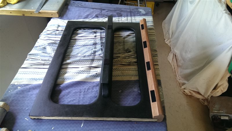
The finished article with some stick on pads to protect the panel
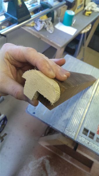
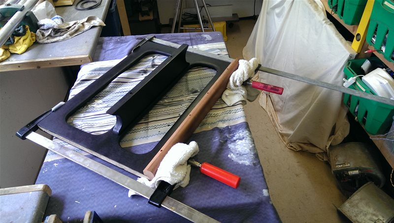
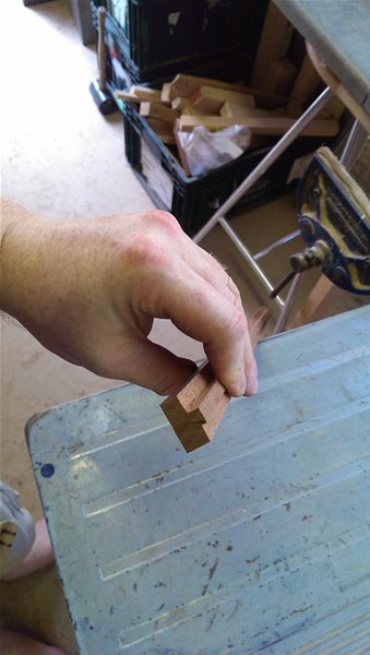
The Centre Trim
Next was the Marquee support. A strip which goes between the control panel and the perspex panel which lights up.
Yet again my router failed me, this time a roller bearing jumped off the strip causing an overly deep cut and my first attempt was wasted 🙁 (I can see myself investing in a bench router before long instead of having to use my handheld one, I guess I better save up!)
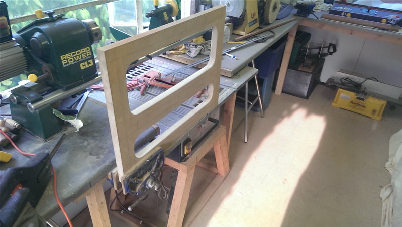
It worked out just right in the end though. I finished the second attempt and fitted it with a gentle tap using a soft mallet. It seated it nicely, protecting the vinyl along the top edge of the control panel perfectly.
First rough cut
In place
Assembled
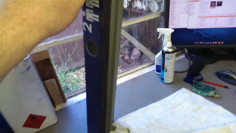
The Sides
The next step was to hit the reclamation yards for some timber to use for the sides. I was really pleased as I managed to get a good deal on half of an old mahogany school desk (which was an inch thick!) Can you imagine trying to buy inch thick mahogany from a DIY shop? Actually can you imagine trying to buy an inch thick sheet of any sort of real wood from a DIY shop? They’d laugh you out the shop. The closest you could get is probably a sheet of chipboard with half a mm of real wood stuck onto it 🙂
Yeah OK I needed to scrape off the chewing gum and put in some power tool time in to get all the old varnish, writing and stains off it, but real wood is worth every bit of effort.
In the end it wasn’t too hard to do, after ripping it down on the saw bench to the correct width, I ran it through my thickness planer a few times.
Of course making the sides curved, smooth and identical was a much more difficult job but I got there in the end 🙂
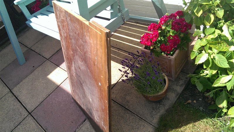
The raw school desk complete with years of abuse in more ways than one 🙂
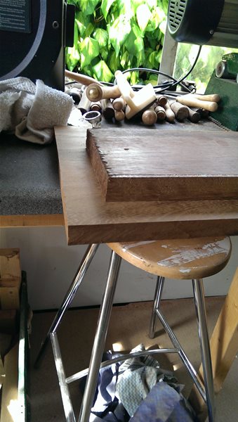
Comparing the original wood to plained smoothed wood.
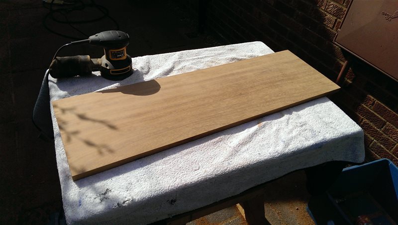
All cleanup and and smoothed off
A finished side
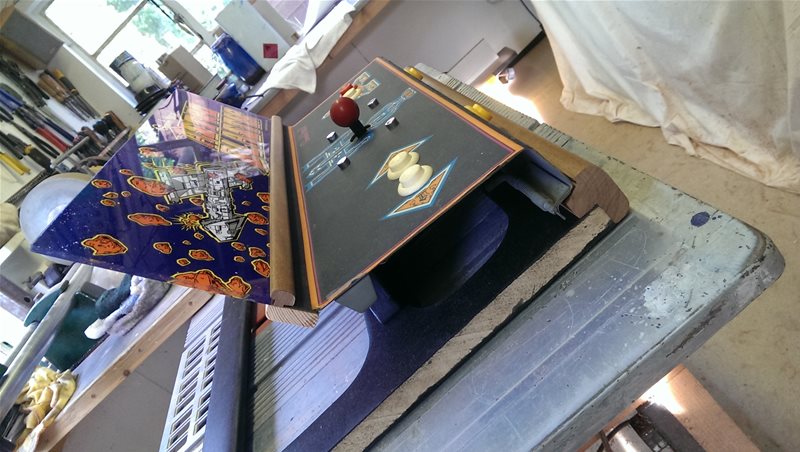
Mock Ups
At this point I was starting to get a bit down about the whole project, all the cutting, routing and sanding I had been doing had taken a lot of time and my fingers were getting blistered, especially after trying to make those two sides identical. The project seemed to be taking forever…
However my amplifier module turned up and a quick mockup reminded me why I was doing it all, it was really starting to look the part 🙂
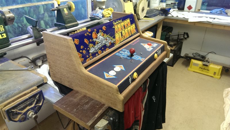
A quick mockup for motivation
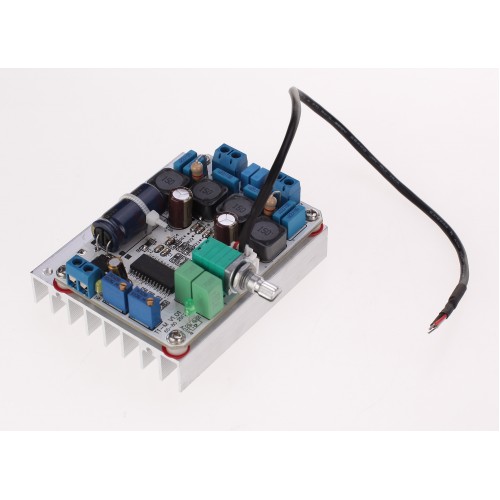
The class D amplifier with plenty of power to shake the cabinet like they did in the old days!
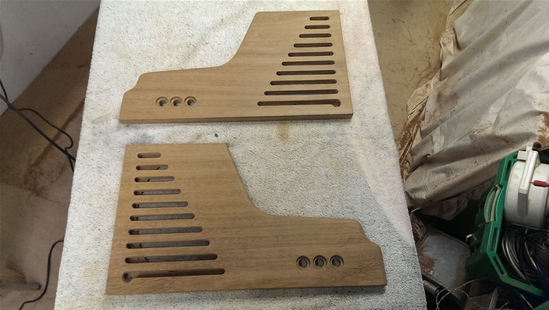
Cutting Out the Louvres and Button Holes in the Sides
After spending ages mocking up different vent ideas by sticking electrical tape strips down the sides I eventually settled on a design. It was hard to come up with an idea as I needed to allow enough venting for the 6×9’s to work properly but not ruin the aesthetics.
Once I had the design drawn on, things started to get really scary. All that work I put into the sides could potentially be ruined with one a little slip, and yet cutting dead straight, correct length and depth louvres without making any mistakes or wibbles was going to be really really hard…
However everything went according to plan (albeit slowly and carefully) with only one little router mishap which I managed to sort…
Lots of painstaking work (oh I wish I had a CNC!)
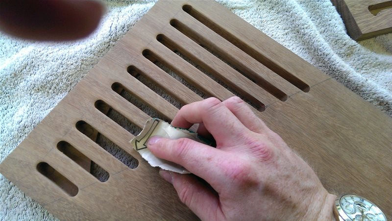
Sanding, sanding and more sanding…
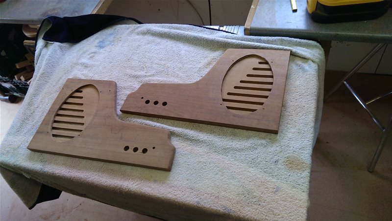
The recesses for the 6×9’s
Staining and Waxing
Next was staining and waxing….
I found a stain which bought the sides closer to the mahogany colour I had used on the front and then waxed them. This was followed by fitting felt behind the buttons so it wasn’t obvious they were square.
It was only after wiring that I discovered Maplin’s buttons were unfortunately poor quality (I know I should have tested first). Even though the red and blue buttons lit up great, the green ones were useless with only a tiny spot lighting up in the middle! I double checked them each individually and all the green buttons were like it. It looks like its basically down to the poor quality LED’s they are using 🙁 At this stage there wasn’t much I could do though as I was running out of time 🙁
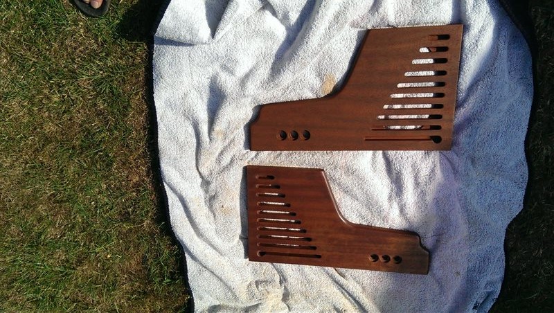
Comparing waxed and stained (bottom) and just plain stained (top)
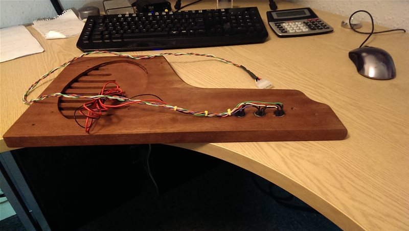
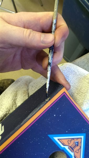
Wiring up the backlit buttons
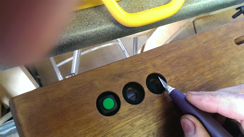
Fitting the felt behind the buttons (yeah I know my thumbs in the way, you try holding a scalpel and taking a photo at the same time 😉 )
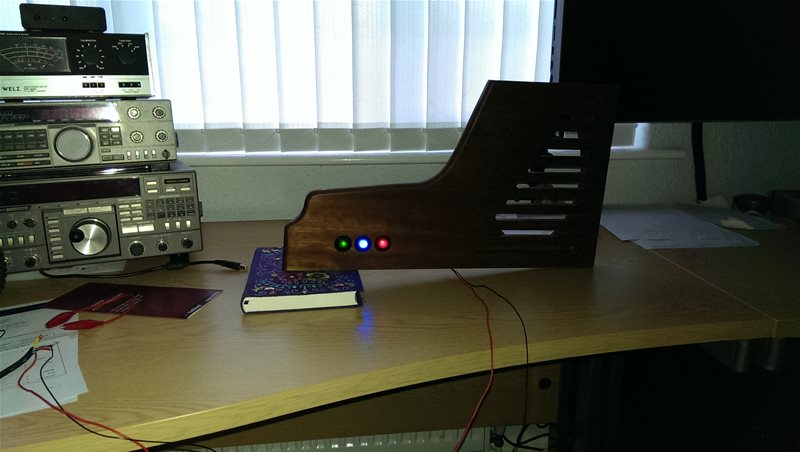
The disappointing uneven illumination 🙁
Assembly
This is where it all started to come together 🙂
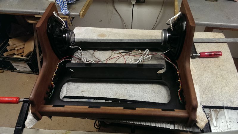
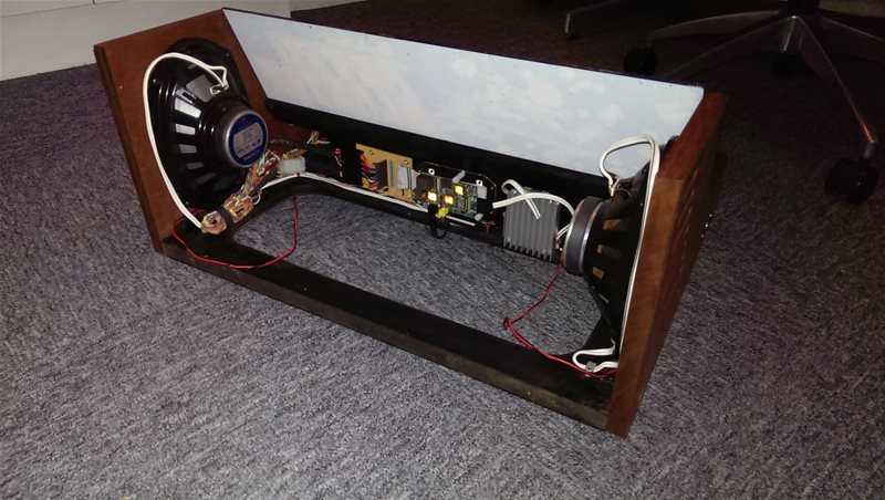
Glueing and screwing the sides with the 6×9’s and pushbuttons in place
A view of the holes in the base which will enable people to see how it works
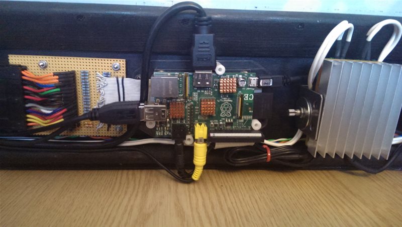
Learning the hard way that Raspberry Pi’s grow up to 3 times their size when you feed them connectors! When you are holding a Pi, its so small its easy to forget that a HDMI plug sticks out further than a Pi is wide!
The excess cable velcro’d on the left is deliberate so it can be taken apart
A the close-up of the grill showing the 6×9 through the louvres. You can’t normally see the speaker, this is an effect of the flash
This photo made me very happy, it was starting to look the biz 🙂
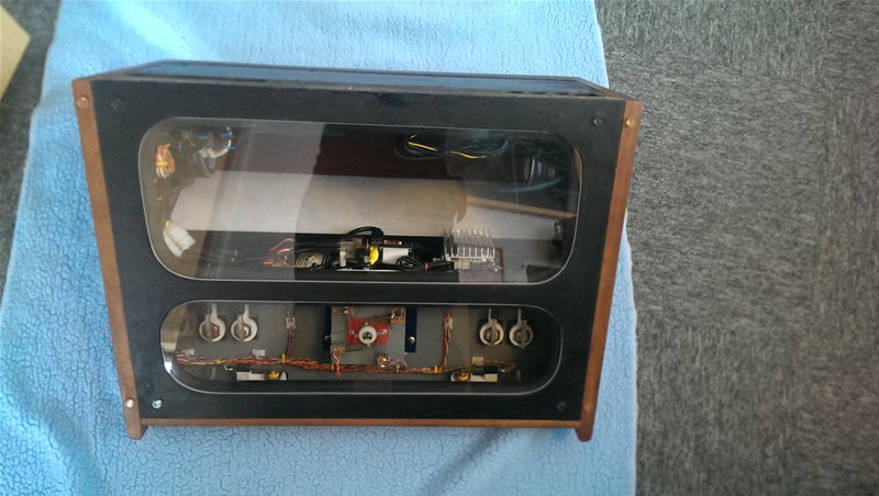
The peak-a-boo panel in the base showing off the glorious vintage electronics (useful for calibrating the buttons and joystick as well!)
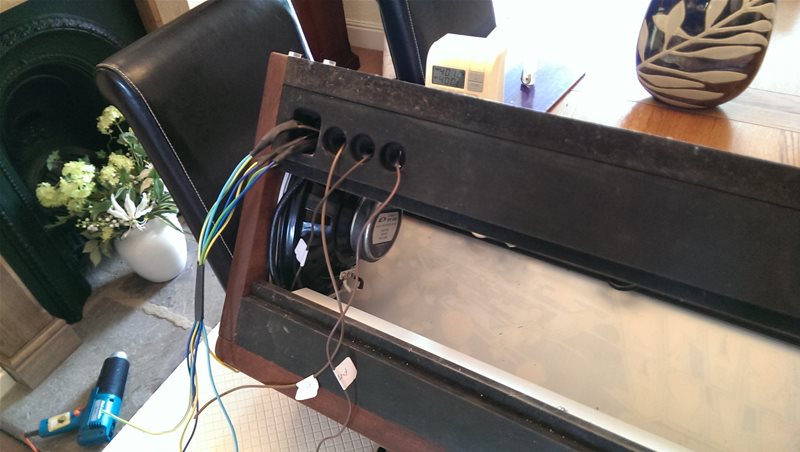
The Back
As much as I didn’t want to get the router out again it was back to work for the sockets, followed by more clamping, glueing and screwing.
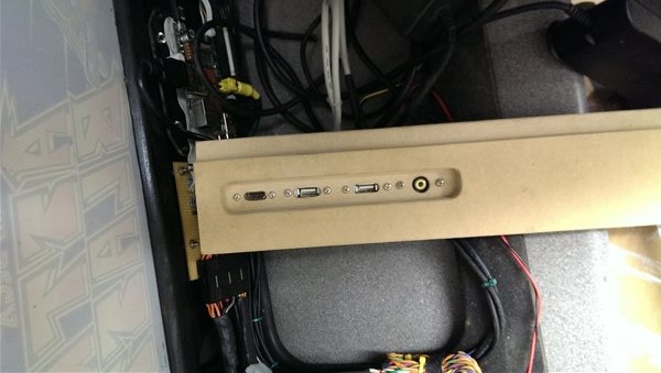
The rear connectors for the HDMI, 2x USB (for external controllers) and composite
More glueing and clamping!
In situ. Above this will go a removable panel
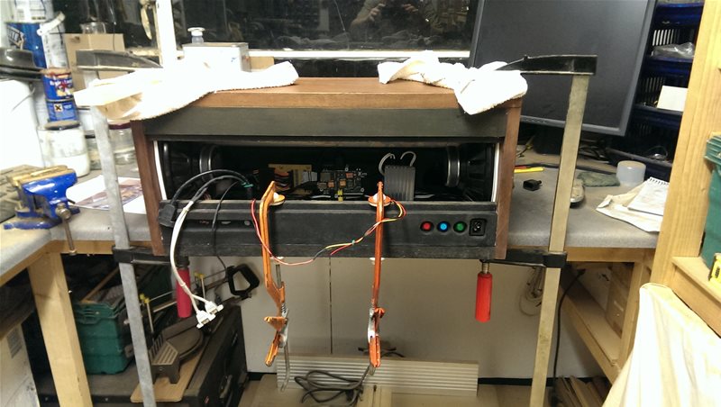
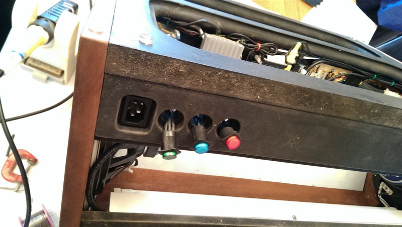
Final Wiring
The last part of the project was the mains wiring. Now normally I would strongly advise that people avoid having mains in their Pi projects but since this project had to have a mains striplight and two power packs (I used an old Dell laptop power pack for the amplifier and an old external hard disk power pack for the Pi) it made sense to have mains inside. For the most part the mains is contained as the power packs are untouched sealed units, but the switches and power socket needed to be wired. For this I made sure I had good solder connections and the wires were thoroughly contained in heatshrink, in some cases with more than one layer!
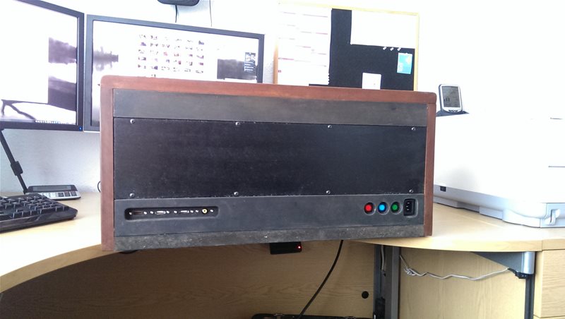
Finished with the rear panel in place and the only visible screws so far 🙂
Lots of heat shrink!
More heat shrink!
Base Perspex and Feet
Next was the perspex in the base which would show the electronics and hopefully bring at least some education benefit to the project 😉 I had been putting this off as I’d never worked perspex before, but it came out OK so I was chuffed 🙂
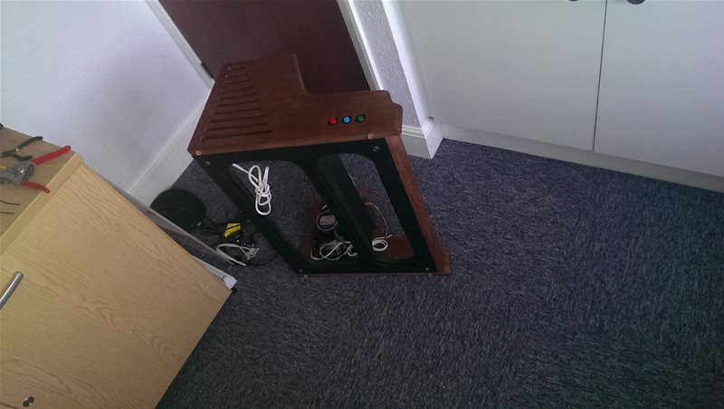
In these photos you can see the original small temporary feet, these were later replaced with some larger rubber feet to give it more stability.
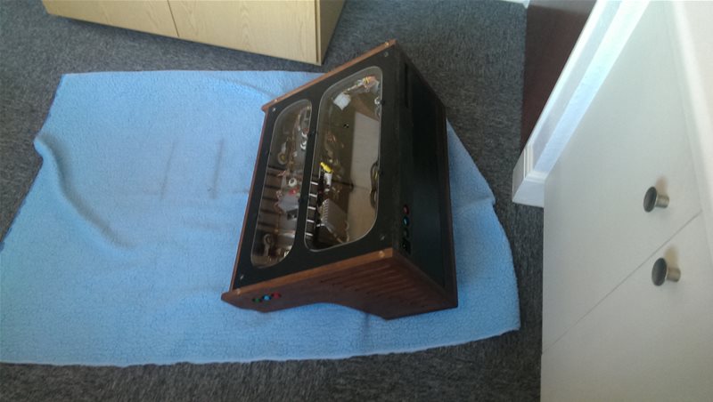
A view showing the Pi in amongst the rest of the electronics
Looking all the way through to the marqee 🙂
You have to love those vintage controls, no microswitches here!
Final Software Tweaks including Overclocking
Now I had it all in one piece and could actually play it, it was time to get the software perfected…
First was the custom loading screen which you can see at the start of this article (shame the telly was in some daft stretch mode and I didn’t get a chance to change it before taking the photo). This was made by photographing the marquee and tweaking it a bit to combine it with the MAME logo, it was simple but effective for the brief period you see it during startup 🙂
After experimentation I settled with the following values, I could maybe have gone higher but this appeared to fix the problems I was having with most games.
ARM: 1GHz (instead of 700MHz)
Core: 500MHz (instead of 250MHz)
RAM: 500MHz (instead of 400MHz)
Voltage: 1.3v (instead of 1.2v)
For testing I used both the SD card tester supplied by the foundation and the memtester command, followed by leaving the machine running games at almost 100% CPU load for 24 hours. It has since done various Raspberry Jam’s and shows without any issues, so I think its about right. With the heatsinks it runs at about 57 degrees with the 4 overvolt (1.3v instead on 1.2v) but to be honest I’ve not tested without the overvolt so I don’t know if its necessary or not, as I said though it seems happy enough so I’ll leave it there.
To be honest I’m very impressed with the Pi’s overclocking ability, I’ve done overclocking in the past on regular PC’s but I don’t think I’ve seen a chip that takes so well to it before. Usually you can get a bit of gain but this is crazy!
For those interested, I am using one of the very first generation 256MB Pi’s (the ones with the dodgy voltage rail, bad polyfuses, etc.) I wasn’t expecting it to do so well so I was really pleased when it did. One other thing people may find interesting is I’m using a micro-SD card instead of the usual full size SD card. I’m not sure how much of a difference that makes but it certainly didn’t hinder anything.
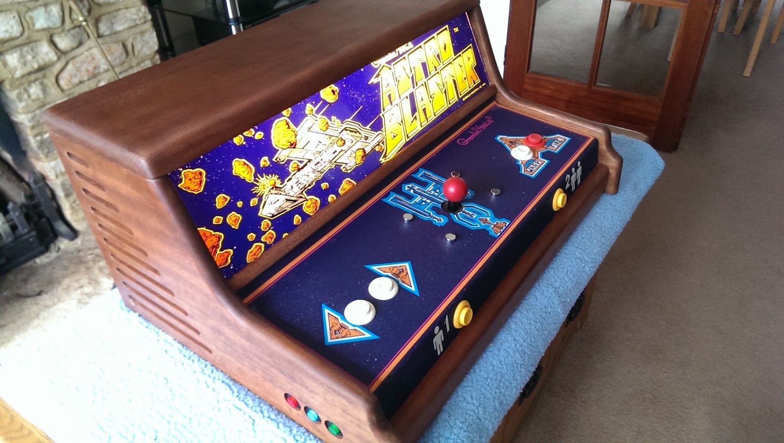
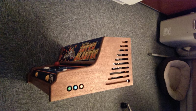
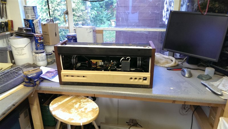
All finished just prior to visiting the Jam’s
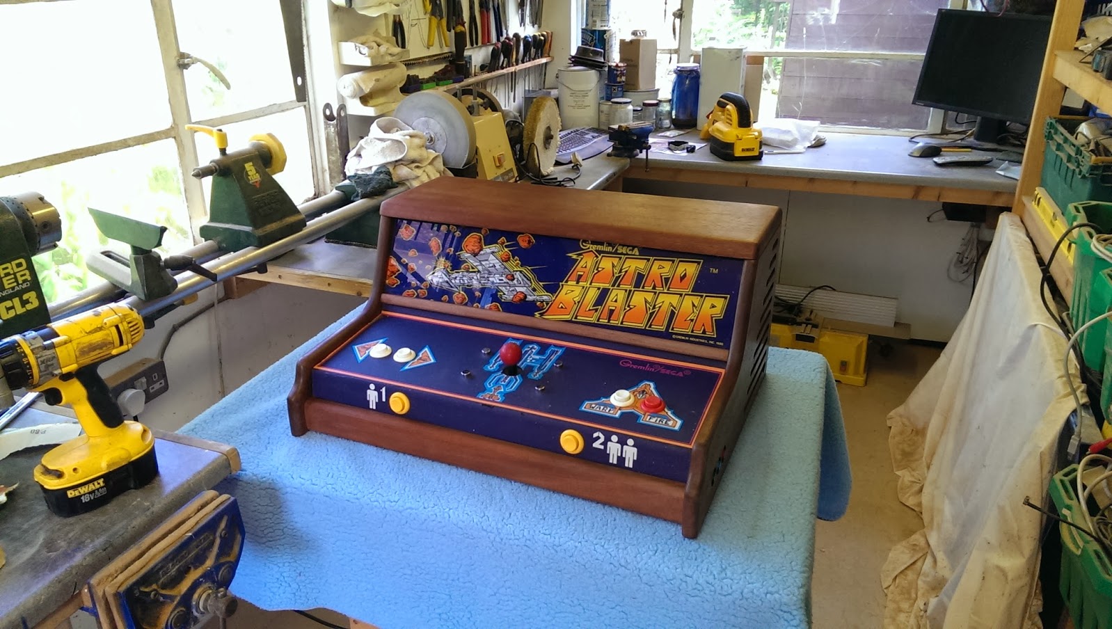
In my workshop
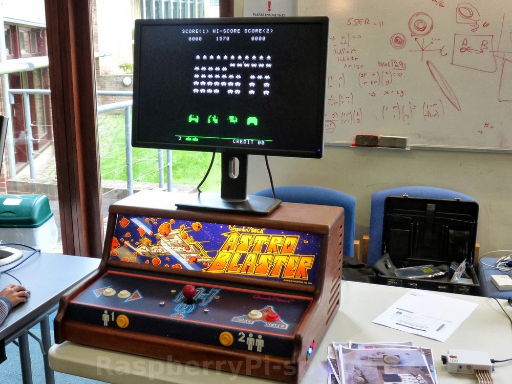
At the Cambridge Jam (picture thanks to http://www.raspberrypi-spy.co.uk/ )
Farewells…
Anyway thats the end of my story. I hope you all enjoyed listening and thanks to those who provided the software that enabled me to do all this! Oh and a special thanks to Mike for letting me borrow his excellent blog for my post 🙂
I hope to talk to you again soon for some more of my projects.
PS: I’ll try and bring AstroBlaster along to as many local Jams as I can so anyone that attends can have a look and a play 🙂
[…] Daniel Bull Due to the unfortunate closure of the Milton Keynes Raspberry Jam; the forum including details of […]