Having followed the flight via live mapping and over the IRC channel, I thought I’d share with you the write-up from the man himself. To recap, Dave Akerman launched a Raspberry Pi inside a TARDIS replica box using a high-altitude balloon on Wednesday, eventually recovering the package in rural Wiltshire.
I’ve been playing around with some stepper motors with driver boards that I bought from eBay. They have a lot of potential and I’m planning to use them on an astronomy project… but more on that later.
The motors were £1.66 each including postage. Not the fastest delivery ever but then they were from Hong Kong.
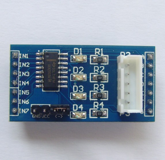
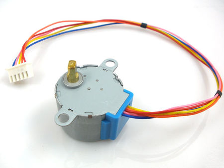
The actual boards which arrived were much nicer than those pictured on the eBay lot and were manufactured by LC Technology. Below is a picture of the actual board and the accompanying stepper motor and cable and here’s a link to the LC Tech page about the board. The stepper motors are all 5V so can be run off the Raspberry Pi’s 5V power supply pin.
Here’s a video of the boards in action:
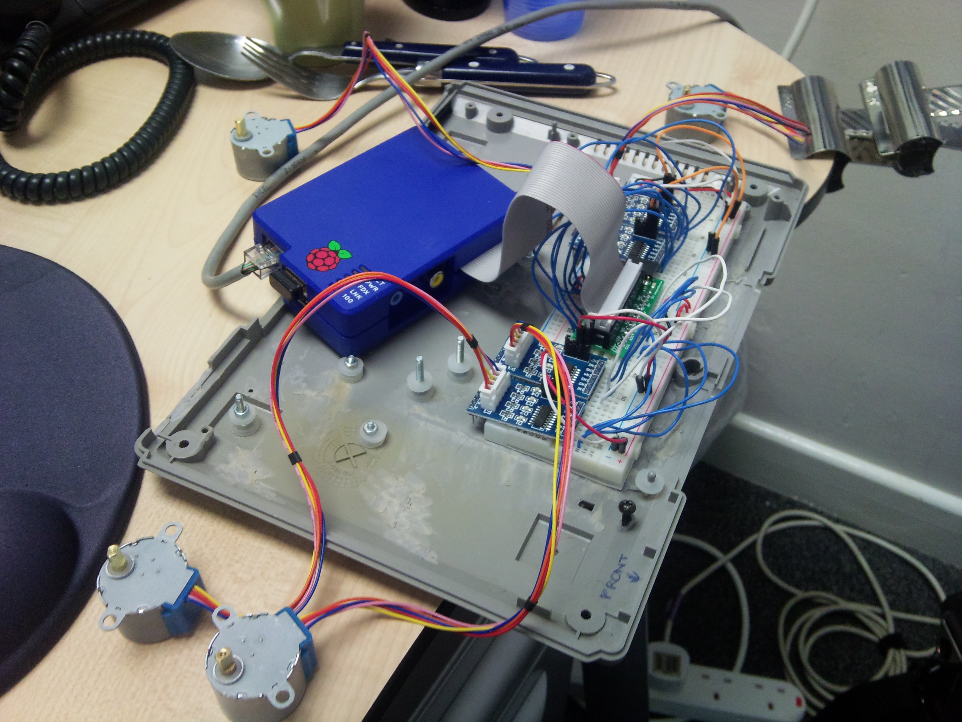
And here’s a still just in case you don’t want to sit through the video! 🙂
I’ve built this on a breadboard connected to the GPIO using a breakout board from HobbyTronics. It’s almost identical to the Pi Cobbler but has a nifty power light and 3.3v regulator on board. Plus they’re based in the UK, which helped with the postage at the time.
As you can probably see, each motor board is run from 4 GPIO pins plus 5V and Ground. I needed male-to-male bell wire for the 4 GPIO connections and male-to-female jumper wires for the power and ground pins that stick up from the board. For those replicating this experiment, your four GPIO wires connect to the pins on the board labelled IN1-IN4. I’ve yet to find out what the other pins do, and there certainly are a lot of them! Note: the control boards are too wide to plug completely into the breadboard but fortunately you don’t use all the pins at one end, so all mine are hanging over the edge. This isn’t great as they tend to pull the breadboard apart a little, but it’ll do for this experiment.
The stepper motors are then connected to the boards using a supplied cable. When the motor is working, the LEDs on the control board light up (in sequence, but they’re going so fast in the video above that you can’t really tell that).
There is a main driver script – test-all-motors.sh – which fires off 4 parallel runs of the test-motor.py script with 4 different sets of 4 GPIO pins.
For those interested, I am using the following physical pins as control pins for the motors: 8,10,12,16 and 18,22,24,26 and 3,5,7,11 and 15,19,21,23. Some of these pins have alternate uses (for example serial tx and rx) but it was necessary to use them as general output pins to get the 16 pins I needed.
What’s next?
Well, at the moment the motors each drive a bit of paper, just to show the movement. However, they have a reasonable amount of torque. So, I’m hoping to use them to control, hopefully on multiple axis, a webcam and eventually an official camera module. This will form the main part of the hardware for an upcoming astronomy project. The code for this is starting to be built as a GitHub repository.
Basic example of a web interface controlling the GPIO. Read the Instructable here. This isn’t as flashy as something like BerryIO but it gives you something basic to work from if you want to provide a web GUI.