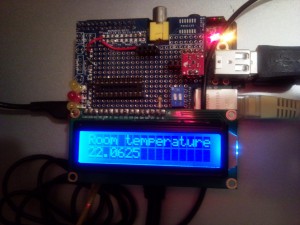
The Picorder project has been progressing, albeit slowly. So far, I’ve managed to add the following items to my Pi:
- a 16×2 LCD board
- a TMP102 temperature sensor
- an SR-04 ultrasonic distance sensor
To start with, I constructed my circuits on a breadboard. This was fine, but I decided I wanted something more permanent and less prone to accidents. Breadboarding is great if you want to be able to easily move wires around when you make a mistake, but of course it also means that the wires come out very easily.
 For this, I went with a Proto-Plate from BitBang.co.uk. The board is very solid, very well-made and has a decent-sized prototyping area. The best thing is that the surface area fits within the Pi’s footprint. The components I added don’t, as you’ll see from the pictures below, but this was never my main concern.
Soldering connections on the board led me to use fine lead solder. This gave me much quicker soldering times and connections that were easier to manage, not mention giving me much tidier results. (Thanks to Peter Onion’s masterclass at the Milton Keynes Raspberry Jam, I’m now soldering properly too.)
Even with the fine solder and improved technique, my wiring (see below) is still a bit untidy, but it has done the job and I’m rather proud of being able to get it working eventually.
I say eventually… Having followed a tutorial on connecting the LCD and found the appropriate resistance for the backlight using a potentiometer, I naturally replaced the pot with a normal resistor. This should have worked… but didn’t. The LCD stubbornly refused to work; It lit up, but no text appeared on it when I ran my scripts. Cue much usage of a multimeter to determine if I’d made the connections correctly. I eventually tracked down the problem and found that, rather than supplying a resistance between the backlight pin and a live contact, the connection should instead be made from the pin to the ground. I’m still not totally sure why, exactly, but rewiring the board to do this finally made it work correctly. The irony is that if I had realised this when I first constructed the circuit, it would have worked first time.

My Picorder (see picture, left) now measures the temperature of the room (well, that part of the room that is near the sensor anyway!) and displays it on the LCD screen.
My next task is to modify the Python script that runs the thing to do an active ultrasonic ‘ping’ to measure distance (this part is already done) and display it on screen (this part isn’t).
